Device for Collecting Flux of Electromagnetic Radiation in the Extreme Ultraviolet

Inactive Publication Date: 2009-10-01
SAGEM DEFENSE SECURITE SA
View PDF8 Cites 11 Cited by
  • Summary
  • Abstract
  • Description
  • Claims
  • Application Information

AI Technical Summary

Benefits of technology

[0046]the concave collector mirror and the convex mirror of the exterior additional collector stage being coated with a multilayer reflective deposition suitable for maximizing the transmission of EUV radiation, said reflective deposition comprising several layers adjusted according to the angle of incidence of the EUV radiation.
[0065]It is furthermore possible to resort to numerous structural expedients in the design of the mirrors, which make it possible to increase the optical quality of the collector device and / or to facilitate the manufacture and reduce the cost of the device. In particular, provision may be made for one at least of the two mirrors of at least one collector stage to be made with an axisymmetric aspherical profile and / or for one at least of the two mirrors of at least the main collector stage (the larger of whose two mirrors may typically have a diameter of the order of 1.10 m) to be made in segmented form.

Problems solved by technology

Collecting the luminous flux delivered by a quasi-pointlike source of electromagnetic radiation such as an arc lamp is not an easy thing to do when one wishes to collect the largest possible quantity of photons emitted by the source in the surrounding space.
Optical microlithography is typically a field for which expensive equipment must produce the largest quantity of silicon microchips per hour by irradiating a photosensitive resin deposited on silicon wafers from which the microchips will thereafter be sliced.
Another characteristic of EUV sources in view of the powers necessary for microlithographic applications is that they deliver many useful photons, but also other undesirable elements:photons situated outside the useful spectral band,ions and other particles ejected at high speed which may erode the surface of the optical elements placed too near the source,diverse debris that is also deposited on the surface of the optical elements of the luminous flux collector device,an intense thermal radiation, partially absorbed by the optical elements of the luminous flux collector device which then undergo undesirable heating.
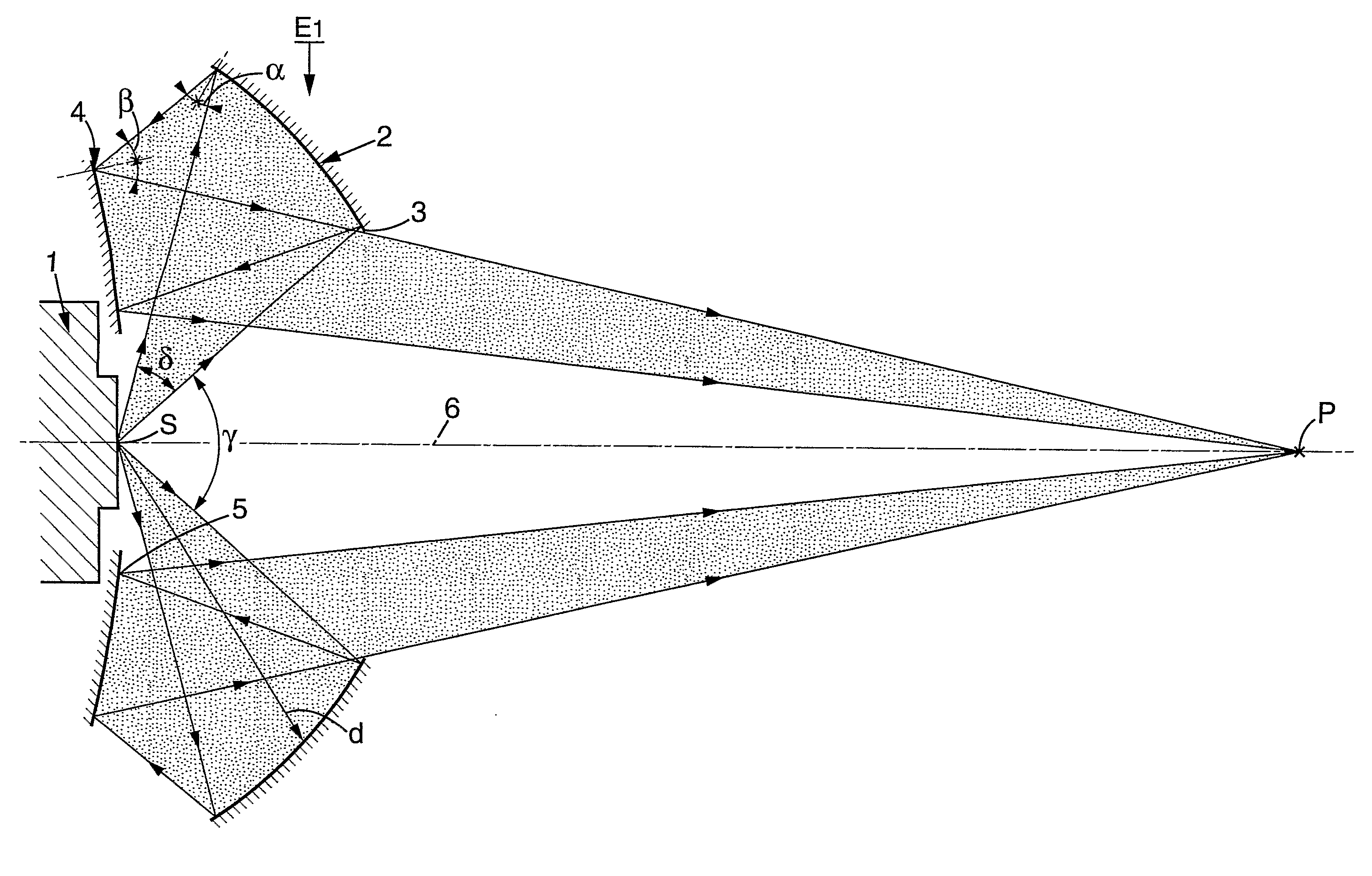
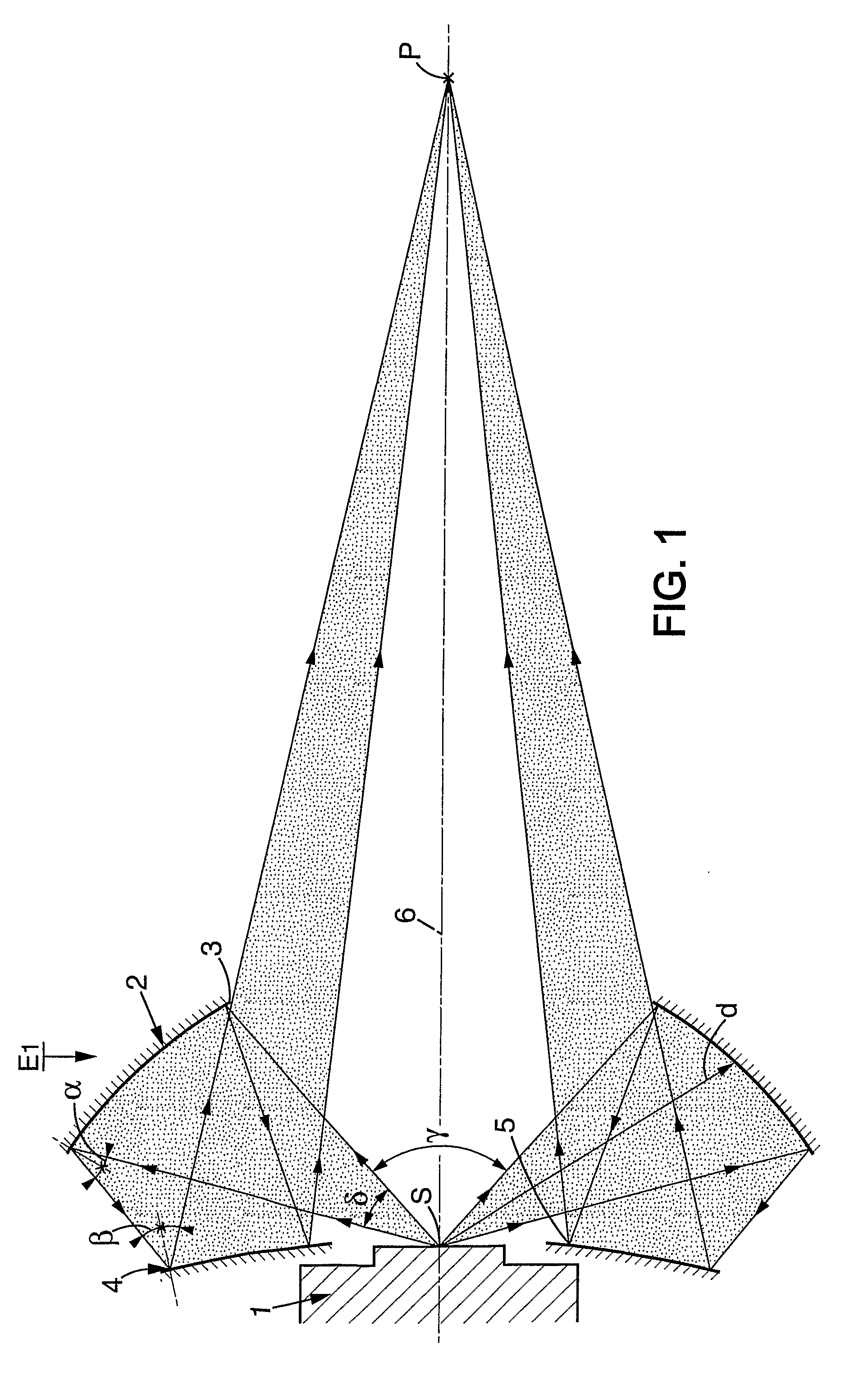
However, it cannot be transposed to the EUV domain for several reasons.
A first reason is that the flux collected is formed with the radiation emitted by the source toward the rear, then reflected toward the front, that is to say it “crosses” the source and is focused in front of the latter; now, EUV sources are complex and bulky devices (typically 30 to 40 cm in diameter for a luminous source point of about 1 mm): a source such as this placed at the focus of the ellipsoidal collector would block the flux reflected by the mirror.
A second reason is to do with the fact that the angles of incidence of the rays on the useful surface of the collector vary greatly according to the location of the reflection on the surface of the mirror, from quasi-normal incidence at the center of the ellipsoidal mirror to almost grazing angles of incidence near the edge of the mirror; treatment of the reflecting surface so as to ensure reflection in the EUV region must therefore entirely change in nature between the center and the edge of the mirror, which is very complex, or indeed impossible, to achieve at least under acceptable economic conditions.
Therefore, despite its advantage in principle, this solution cannot be employed.
Another drawback of this known technique is that, to pick up a significant portion of the light emitted by the source, the first elements must be brought near to the source: in devices made on the basis of this principle, the first optical elements are placed at a distance of 10 to 15 cm from the source and attacks by erosion, contamination or heating then become very serious; the effective lifetime of the collector device remains limited (see for example document US 2005 / 094764).
This arrangement suffers from insufficient luminous collection effectiveness and does not constitute an appropriate response to the problem posed, in particular on account of the high angles of incidence of the rays arriving at the second convex mirror.
This known device suffers from a lack of luminous collection effectiveness due to a limitation of the optical extent collected by the large mirror and due also to too close a proximity of the secondary mirror to the source itself, which hampers the course of the rays, as well as to the presence of various devices intended for capturing or deflecting the particles or debris emitted by the source.
The major drawback of this known solution is that it is inappropriate for sources of the “Capillary Discharge Plasma” type, since the optical path passes through the source, precisely where the optical, mechanical and electronic components operating the source are housed.
This known device therefore has limited conditions of use which may be inappropriate within the context of a microlithography installation.
This known device does not provide an effective response and does not obviate the resulting drawback of the high degree of deformation of the optics under the thermal flux of the source.
In a general manner, none of the currently known devices is capable of collecting an appreciable fraction of the luminous flux emitted by the source, and their effectiveness remains limited to a few percent and / or they are arranged in a manner such that some at least of their components are rapidly impaired and / or they are too cumbersome for the application more specifically envisaged in the field of microlithography.
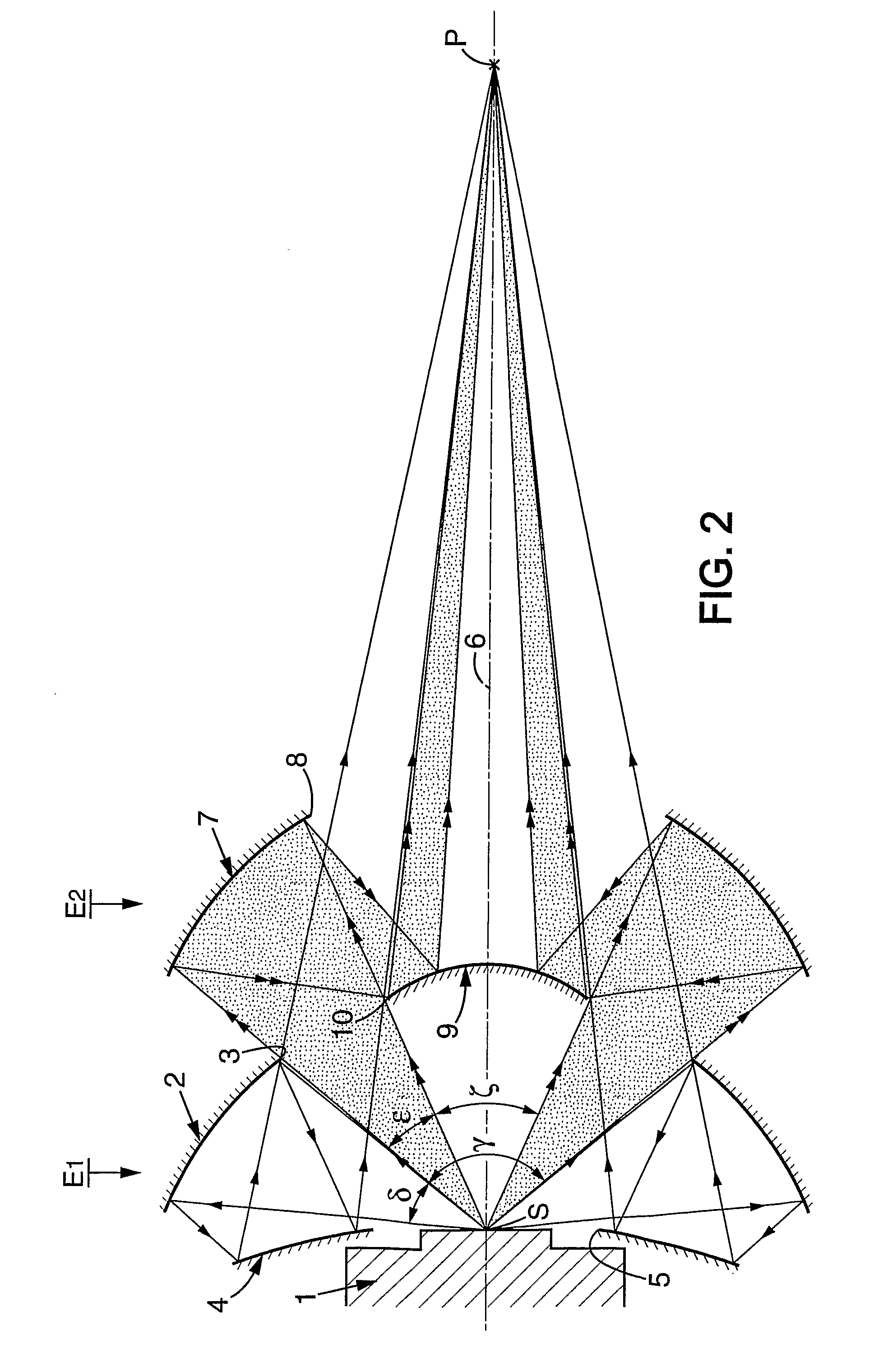
The constraints inherent in integrating the collector device into a microlithography machine operating with an EUV source should also be remembered: impossibility of implementing optical lenses, no material being transparent for these wavelengths, and necessity of implementing reflecting optical components only; bulky source which requires that the entire optical collection hardware be situated in front of this source; very congested environment which leaves only a restricted free space for setting up the optical collection components; focusing distance (typically of the order of 1.20 m) which is not capable of being appreciably lengthened because of the constraints of general congestion within the machine.

Method used


Image

  • Device for Collecting Flux of Electromagnetic Radiation in the Extreme Ultraviolet
  • Device for Collecting Flux of Electromagnetic Radiation in the Extreme Ultraviolet
  • Device for Collecting Flux of Electromagnetic Radiation in the Extreme Ultraviolet

Examples


Embodiment Construction

[0071]Reference is first made to FIG. 1 which illustrates a device for collecting electromagnetic radiation having a wavelength situated in the EUV extreme ultraviolet—that is to say, less than about 150 nm, and typically 13.5 nm within the framework of application to a microlithography machine—which is emitted by a source S. Although in the optical diagram the source S is depicted in pointlike form, such a source is, in practice, a very bulky device as shown diagrammatically as 1.

[0072]The collector device represented in FIG. 1 comprises a single collector stage, which will be termed the main collector stage, designated by E1, which is constructed as follows.

[0073]A concave collector mirror 2, provided with a central through-hole 3, is placed in front of the source S, its concavity being directed toward the source S. The concave mirror 2 is suitable for receiving a part of the flux emitted by said source S and for reflecting this flux toward a point situated at the rear of the sour...


PUM


Abstract

Device for collecting a flux of electromagnetic radiation in the extreme ultraviolet (EUV) emitted by a source (S), comprising a main, first collector stage (E1), with a concave collector mirror (2) placed in front of the source (S) at a distance of greater than 250 mm and pierced by a central hole (3) and a convex mirror (4) placed behind the concave mirror level with the source and pierced by a central hole (5), and at least a second collector stage (E2) with a concave collector mirror (7) placed in front of the stage (E1) and pierced by a central hole (8) and a convex mirror (9) placed behind the concave mirror.

Description

CROSS REFERENCE TO RELATED APPLICATIONS[0001]This application is the U.S. national phase of International Application No. PCT / FR2007 / 000573 filed on Apr. 4, 2007 and published in French on Oct. 25, 2007 as International Publication No. WO2007 / 118993 A1, which application claims priority to French Patent Application No. 0603116 filed on Apr. 7, 2006, the contents of both of which are incorporated herein by reference.FIELD OF THE INVENTION[0002]The present invention relates in a general way to the field of illumination with electromagnetic radiation situated in the extreme ultraviolet EUV and, more precisely, the invention relates to refinements made to devices for collecting electromagnetic radiation flux in the extreme ultraviolet (EUV) emitted by a source of EUV electromagnetic radiation, said devices comprising at least one collector stage arranged as set forth in the preamble of claim 1.BACKGROUND OF THE INVENTION[0003]The expression “extreme ultraviolet” is understood to denote ...

Claims


Application Information

Patent Timeline
IPC IPC(8): G02B5/10
CPCG03F7/70175
Inventor GEYL, ROLANDPATOZ, VINCENTRIGUET, FRANCOISDUFRESNE DE VIREL, FRANCOIS
Owner SAGEM DEFENSE SECURITE SA
Why Eureka
Try Eureka