Insert clamping wedge and insert-detachable type cutter

a clamping wedge and insert technology, applied in the field of insert clamping wedges, can solve the problems of limited gap between the insert attachment seat and the recessed portion, deformation or damage of the thinned portion, and deterioration of the clamping strength, so as to prevent the cutter body from deformation or damage, increase the number of cutting blades, and improve the clamping strength

Active Publication Date: 2009-10-01
MITSUBISHI MATERIALS CORP
View PDF8 Cites 2 Cited by
  • Summary
  • Abstract
  • Description
  • Claims
  • Application Information

AI Technical Summary

Benefits of technology

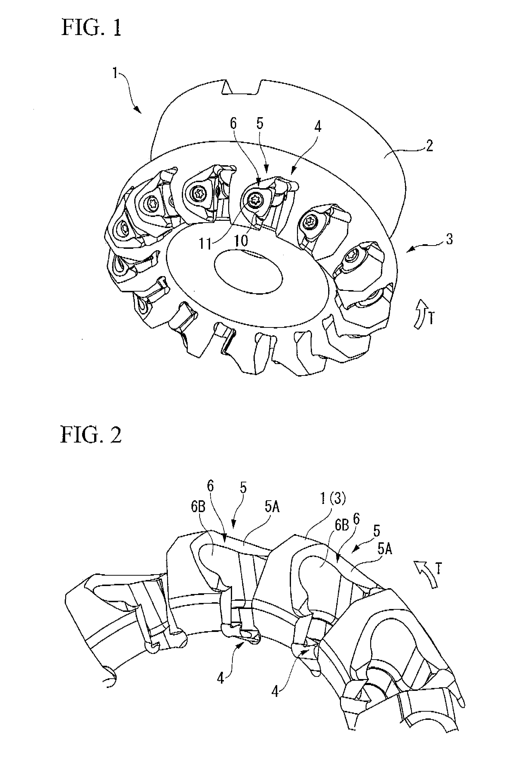
[0012]In the clamp wedge and the insert-detachable type cutter according to the present invention, the sectional shape perpendicular to the press-insertion direction of the wedge body is formed in a bell shape. That is, in the wedge surface of the wedge body, both ends of the protruded curve form a recessed curve to thereby form a narrowed shape. Accordingly, even when the width of the clamp surface increases to ensure a large area, it is possible to prevent the sectional area of the wedge body and the recessed portion perpendicular to the press-insertion direction from excessively increasing. As a result, it is possible to cope with an increase in the number of cutting blades by using the clamp wedge according to the present invention. Also, in the insert-detachable type cutter according to the present invention, the clamp wedge according to the present invention is used. Accordingly, even when the number of cutting blades increases, it is possible to prevent the cutter body from being deformed or damaged by maintaining the thickness in the periphery of the recessed portion of the cutter body and to strongly fix the cutting insert by improving the clamping strength.
[0013]Further, in the section perpendicular to the press-insertion direction, the wedge surface of the wedge body of the clamp wedge is formed by a region from the protruded curve portion to at least the recessed curve portions in both ends thereof. That is, the gap between the wedge surface and the clamp surface becomes smaller in the press-insertion direction of the wedge body. With such a configuration, it is possible to reliably apply the pressing force from both ends of the wedge surface to the opposite-side clamp surface by pressing the wedge body. Accordingly, in the clamp wedge according to the present invention, it is possible to strongly fix the cutting insert in a stabler manner.
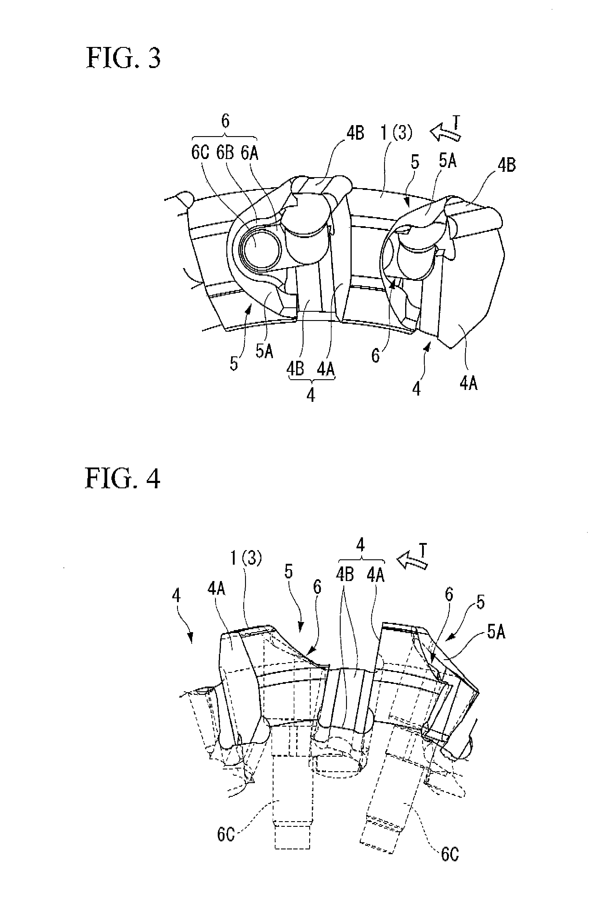
[0014]Meanwhile, in order to prevent deterioration of the clamping strength described above in the circular cutter body of the insert-detachable type cutter, the cutter body may have the following configuration. That is, in a section perpendicular to the press-insertion direction, each of opening peripheries of the recessed portion of the cutter body are formed in a recessed surface which rises up in a direction opposite to the press-insertion direction as the distance from the clamping wedge in a diameter direction of the cutter body becomes greater. Accordingly, even when the gap between the insert attachment seat and the recessed portion is limited due to the increase in the number of cutting blades, it is possible to ensure a large thickness in both ends of the periphery of the recessed portion of the cutter body in the press-insertion direction. As a result, it is possible to improve the clamping strength by ensuring the rigidity of the periphery of the recessed portion of the cutter body.
[0015]In addition, when the recessed portion is located on the side of the rake face of the cutting insert fixed to the insert attachment seat, the opening periphery of the recessed portion, of which rises up to be formed in a recessed surface shape, may be formed in a recessed curve shape. With such a configuration, it is possible to increase the capacity of the chip pocket formed by the opening periphery and the wedge body by ensuring the rigidity of the cutter body as described above. Accordingly, it is possible to smoothly discharge small fragments produced by the cutting blade of the cutting insert and the abrading the rake face.
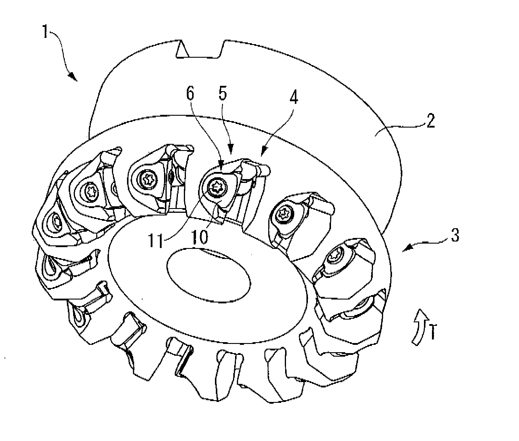
[0016]As described above, according to the present invention, it is possible to maintain the small thickness of the cutter body by preventing the sectional area of the wedge body or the recessed portion from increasing even in the insert-detachable type cutter having a plural of blades. Accordingly, according to the present invention, it is possible to prevent a deformation or damage of the cutter body and to improve the clamping strength. In addition, since it is possible to obtain the clamp surface having a large area by enlarging the width of a clamp surface of the clamp wedge, the cutting insert can be strongly fixed. As a result, it is possible to efficiently and highly precisely carry out a cutting process in a stable manner.

Problems solved by technology

Accordingly, when the clamp wedge is pressed so as to clamp the insert, the clamping strength may deteriorate or the thinned portion may be deformed or damaged.
However, in the case where the number of cutting blades increases, the gap between the insert attachment seat and the recessed portion is limited.
As a result, it is difficult to form the recessed portion having a large area described above.

Method used


Image

  • Insert clamping wedge and insert-detachable type cutter
  • Insert clamping wedge and insert-detachable type cutter
  • Insert clamping wedge and insert-detachable type cutter

Examples


Embodiment Construction

[0036]FIGS. 1 to 14 are views showing a clamp wedge and an insert-detachable type cutter according to an embodiment of the present invention. In the insert-detachable type cutter according to this embodiment, a cutter body 1 is formed of steel or the like so as to have a substantially disc shape as shown in FIG. 1. The rear end side (the upper side of FIG. 1) of the cutter body 1 in a central axial direction is formed as an attachment portion 2 which is attached to a main shaft of a machine tool. The front end side (the lower side of FIG. 1) of the cutter body 1 is formed as a blade portion 3 having a diameter larger than that of the attachment portion 2 by one level. The cutter body 1 is configured to rotate about the central axis in a cutter rotation direction T so as to be used in which a workpiece is cut.

[0037]The front-end outer peripheral side of the blade portion 3 is provided with an insert attachment seat 4 which is formed by cutting the rear-end inner peripheral side of th...


PUM


Abstract

An insert clamping wedge for clamp-fixing a cutting insert, seated in an insert attachment seat formed in a cutter body, to a recessed portion formed in the insert attachment seat is provided, the insert clamping wedge including: a wedge body, wherein the insert clamping wedge is pressed into the cutter body, wherein the wedge body includes a clamp surface which comes into close contact with the cutting insert and a wedge surface of which a gap between itself and the clamp surface becomes smaller in a press-insertion direction of the wedge body, and wherein the section perpendicular to the press-insertion direction of the wedge body from the wedge surface to the clamp surface being formed in a bell shape.

Description

BACKGROUND OF THE INVENTION[0001]1. Field of the Invention[0002]The present invention relates to an insert clamping wedge (hereinafter, referred to as a clamp wedge) which is used to detachably clamp-fix a cutting insert to an insert attachment seat of a cutter body in an insert-detachable type cutter such as a face mill and also relates to an insert-detachable type cutter which is mounted with the clamp wedge so as to attach the cutting insert thereto.[0003]Priority is claimed on Japanese Patent Application No. 2008-88334, filed Mar. 28, 2008, the content of which is incorporated herein by reference.[0004]2. Description of Related Art[0005]An insert-detachable type cutter using a clamp wedge is disclosed in, for example, Japanese Examined Patent Application Publication, Second Publication No. H01-44443, Japanese Unexamined Patent Application, First Publication No. H01-295709, and PCT International Publication No. WO 2008 / 023361. The insert-detachable type cutter includes a cutter b...

Claims


Application Information

Patent Timeline
Patent Type & Authority Applications(United States)
IPC IPC(8): B23C5/22B23C5/20
CPCB23C5/2269B23C2210/206Y10T407/1938Y10T407/1922Y10T407/2284Y10T407/2256Y10T407/1906Y10T407/1924B23C5/2239B23C5/2247B23C2210/16B23C2210/24
Inventor HAYASHIZAKI, HIROAKIHOKI, HIROSHI
Owner MITSUBISHI MATERIALS CORP
Why Eureka
Try Eureka