Pump of electronically controlled brake system

a technology of electronic control and brake pedal, which is applied in the direction of positive displacement liquid engine, piston pump, liquid fuel engine, etc., can solve the problems of abnormal tactile feedback of the brake pedal, increase in manufacturing costs for processing and assembly of the above elements, and noise in the operation of the conventional pump, so as to improve the formability and reduce manufacturing costs

Active Publication Date: 2009-10-01
HL MANDO CORP
View PDF8 Cites 12 Cited by
  • Summary
  • Abstract
  • Description
  • Claims
  • Application Information

AI Technical Summary

Benefits of technology

[0016]Accordingly, it is an aspect of the invention to provide a pump of an electronically controlled brake system, which can achieve an improved formability and reduced manufacturing costs.
[0017]It is a further aspect of the invention to provide a pump of an electronically controlled brake system, which can reduce pulsation of fluid that flows through a discharge valve, thereby reducing operation noise thereof and improving tactile feedback from a brake pedal.

Problems solved by technology

However, in the above-described conventional pump of an electronically controlled brake system, due to a complicated configuration of the outlet valve, in particular, of the valve seat 21, pump plug 22, etc., there is a problematic increase in manufacturing costs required for processing and assembly of the above elements.
Further, the conventional pump suffers from operation noise caused by pulsation of fluid that flows through an outlet path according to opening / closing operations of the outlet valve.
The fluid pulsation also results in abnormal tactile feedback from a brake pedal.

Method used


Image

  • Pump of electronically controlled brake system
  • Pump of electronically controlled brake system
  • Pump of electronically controlled brake system

Examples


first embodiment

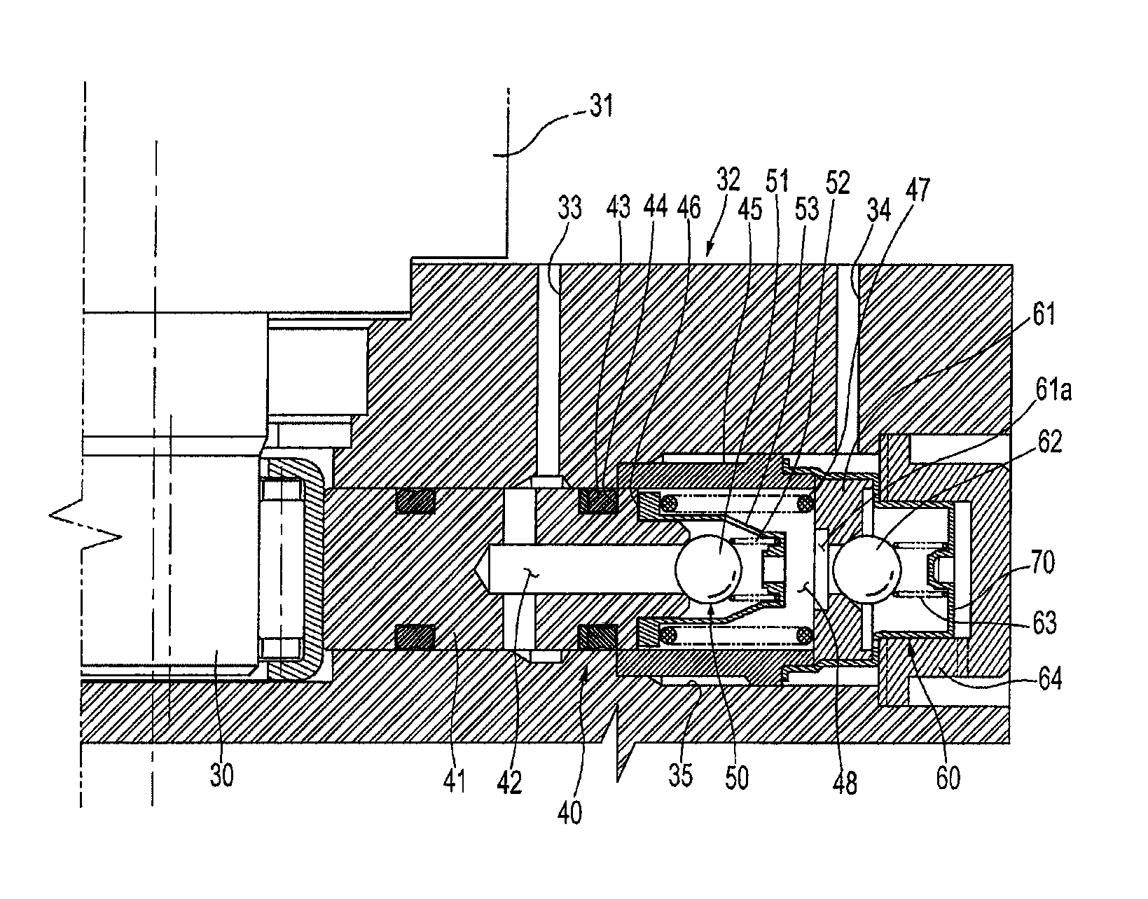
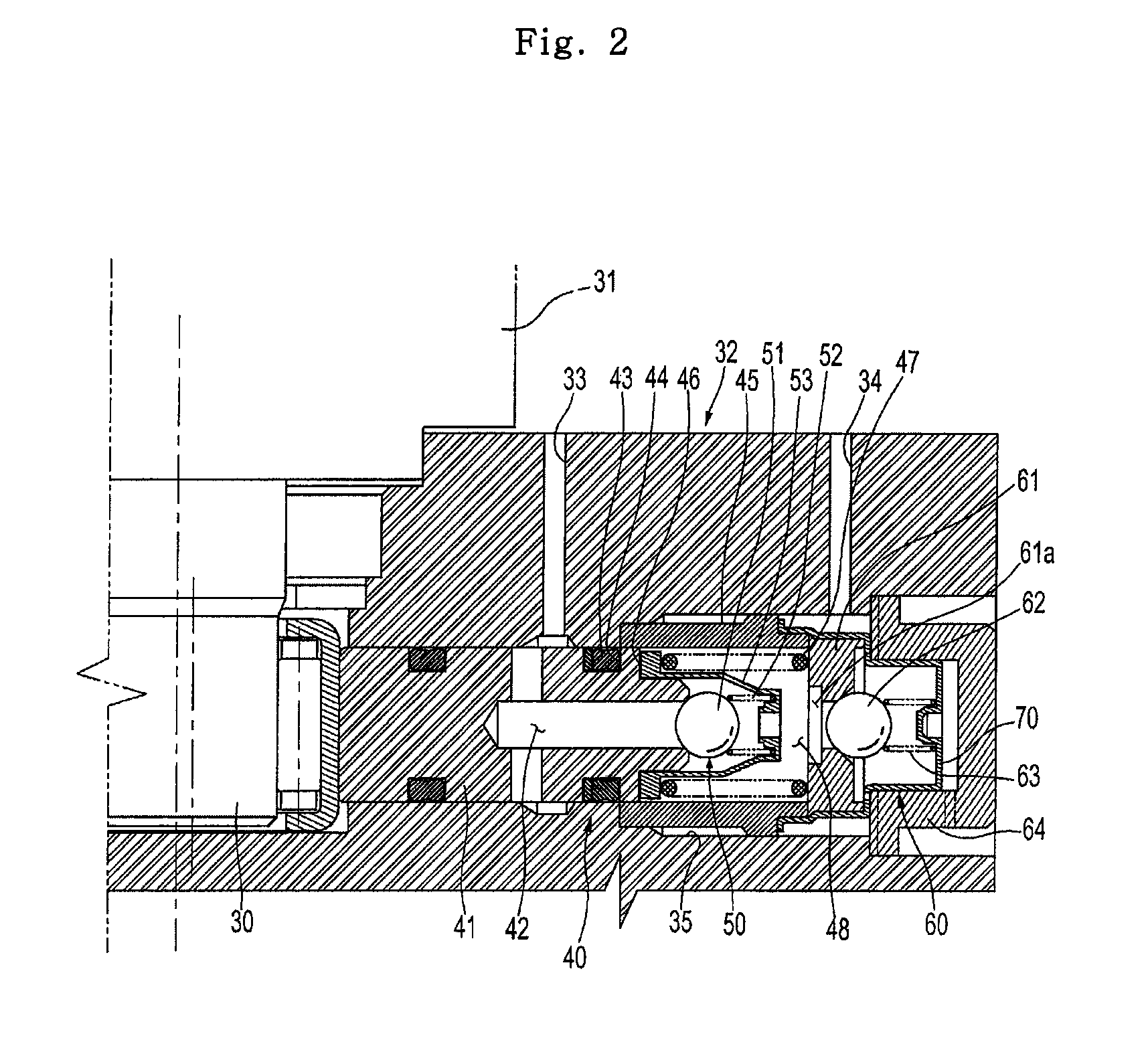
[0035]FIG. 2 is a sectional view showing a pump of an electronically controlled brake system in accordance with the present invention. FIG. 3 is a perspective view of a sleeve included in the pump shown in FIG. 2.

[0036]As shown in FIG. 2, an electronically controlled brake system according to the present invention basically includes a pair of piston pumps 40, which are arranged opposite to each other about an eccentric spindle 30 of a motor 31. The pumps 40 perform pumping operations, having a phase difference of 180° from each other, when the eccentric spindle 30 of the motor 31 rotates eccentrically. Since the pair of piston pumps 40, arranged in a line, have the same configuration as each other, hereinafter, only one of the piston pumps 40 will be described for clarity of description.

[0037]The piston pump 40 is inserted in a bore 35 defined in a modulator block 32 to rectilinearly reciprocate in the bore 35 by rotation of the eccentric spindle 30 of the motor 31. The piston pump ...

second embodiment

[0052]Now, the present invention will be described in detail with reference to the accompanying drawings.

[0053]FIG. 4 is a sectional view showing a pump of an electronically controlled brake system in accordance with a second embodiment of the present invention. FIG. 5 is a perspective view of a sleeve included in the pump shown in FIG. 4. FIG. 6 is a perspective view of the sleeve shown in FIG. 5, as seen from a different angle than in FIG. 5.

[0054]As shown in FIG. 4, an electronically controlled brake system according to the second embodiment of the present invention basically includes a pair of piston pumps 140, which are arranged opposite to each other about an eccentric spindle 130 of a motor 131. The pumps 140 perform pumping operations, having a phase difference of 180° from each other, when the eccentric spindle 130 of the motor 131 rotates eccentrically. Since the pair of piston pumps 140, arranged in a line, have the same configuration as each other, hereinafter, only one ...

third embodiment

[0073]Now, the present invention will be described in detail with reference to the accompanying drawings.

[0074]FIG. 7 is a sectional view showing a pump of an electronically controlled brake system in accordance with a third embodiment of the present invention. FIG. 8 is a sectional perspective view of a sleeve included in the pump shown in FIG. 7. FIG. 9 is a perspective view of a valve cap included in the pump shown in FIG. 7.

[0075]The third embodiment of the present invention is identical to the above-described second embodiment except for the configuration of the outlet valve. Therefore, the same configurations as those of the second embodiment are designated by the same reference numerals, and a description thereof will be omitted.

[0076]In the pump of an electronically controlled brake system according to the third embodiment of the present invention, as shown in FIG. 7, an outlet valve 260 is located, about the piston 141, at an opposite side of the eccentric spindle 130.

[0077...


PUM


Abstract

A pump of an electronically controlled brake system. The pump includes a bore formed in a modulator block and connected with a suction port and a discharge port, a piston installed in the bore in a reciprocating movable manner and defining an inlet path therein, an inlet valve to open or close an exit-side end of the inlet path according to a position of the piston, and an outlet valve provided at one side of the bore, operations of the inlet and outlet valves being contrary to each other. The outlet valve includes a valve seat, a sleeve to surround the valve seat, an outlet ball interposed between the sleeve and the valve seat and used to open or close a path defined in the valve seat, and a valve cap provided at one side of the sleeve to isolate an interior from an exterior of the bore. One or more of the valve sheet, sleeve, and valve cap are formed by press-forming, to achieve improved assembly efficiency and reduced manufacturing costs.

Description

BACKGROUND OF THE INVENTION[0001]1. Field of the Invention[0002]The present invention relates to a pump of an electronically controlled brake system, and, more particularly, to a pump of an electronically controlled brake system in which an outlet valve has a simplified configuration, thereby achieving a reduction in manufacturing costs.[0003]2. Description of the Related Art[0004]In general, an electronically controlled brake system has the purpose of efficiently preventing a wheel slip caused upon braking, quick start, or sudden acceleration of a vehicle. The brake system includes a plurality of solenoid valves to control a braking hydraulic pressure to be transmitted to hydraulic brakes of vehicle wheels, a pair of low-pressure and high-pressure accumulators to temporarily store an oil discharged from the hydraulic brakes, a pair of pumps provided between the low-pressure and high-pressure accumulators, the pumps being operated by a motor, and an ECU to control operations of the ...

Claims


Application Information

Patent Timeline
Patent Type & Authority Applications(United States)
IPC IPC(8): F04B7/04
CPCB60T8/4031B60T11/232F04B53/1002F04B1/0452B60T17/02Y10T137/7927
Inventor KIM, YONG KAP
Owner HL MANDO CORP
Why Eureka
Try Eureka