Engine Revolutions Control Device of Working Vehicle and Method

a technology of working vehicle and control device, which is applied in the direction of machines/engines, fluid gearings, and gearings, etc., can solve the problems of low-speed running, troublesome forward/reverse changeover, and inability etc., to achieve the effect of reducing the braking effect, unable to perform work efficiently, and unable to achieve expected braking

Active Publication Date: 2009-10-01
KOMATSU LTD
View PDF10 Cites 19 Cited by
  • Summary
  • Abstract
  • Description
  • Claims
  • Application Information

AI Technical Summary

Benefits of technology

[0012]Here, when the shift range “2” is selected at the time of working to make the forward / reverse changeover at a low speed, control may be made not to cause an automatic gear change to the speed gear (third speed gear) of a higher speed than the maximum speed gear (second speed gear) in the shift range in order to enhance the braking effect. But, if the vehicle speed increases during the work, the vehicle is in a running state at the second speed gear regardless of the vehicle speed region of the third speed gear, the revolutions of the forward clutch or the reverse clutch becomes excessive, and a heat generation amount of the clutch exceeds an acceptable amount. Therefore, the clutch has an excessive heat load, and the durability of the clutch is adversely affected. To avoid it, the clutch must be made to have a large capacity to deal with the excessive heat load, the clutch has a large size and the cost is increased.
[0013]The present invention has been made under the circumstances described above and provides the braking effect by the low-speed speed gear as expected by the operator at the time of forward / reverse changeover and also enhances the durability of the clutch without increasing the capacity of the clutch.
[0030]As a result, when a wheel loader 100 is running at the forward second speed “F2” as shown in FIG. 2 as indicated by an arrow A according to the characteristic L1, the engine target revolutions are gradually decreased as the vehicle speed V is increased and when V reaches an upper limit vehicle speed Vm, the revolutions are limited to the number of revolutions Nef which is 87% of the maximum number of revolutions Nem. Therefore, even if the accelerator pedal 11 is depressed to 100%, the number of revolutions of the engine 1 is limited to the number of revolutions Nef which is 87% of the maximum number of revolutions Nem, and the vehicle speed V does not exceed the upper limit vehicle speed Vm of the second speed gear.
[0032]Thus, the braking effect by the low-speed gear (second speed gear) can be obtained as expected by the operator, and the work can be made efficiently and swiftly. And, since the engagement changeover between a forward clutch 25 and a reverse clutch 26 is not performed when the vehicle speed V exceeds the upper limit vehicle speed Vm of the second speed gear, a heat load applied to the clutch is decreased, the durability of the clutch is improved, the clutch capacity can be decreased, the clutch is made compact, and the cost is reduced.

Problems solved by technology

The troublesome forward / reverse changeover at low-speed running is performed not only at the time of the V-shape loading but also at the time of loading a cargo on a ship by the wheel loader.

Method used


Image

  • Engine Revolutions Control Device of Working Vehicle and Method
  • Engine Revolutions Control Device of Working Vehicle and Method
  • Engine Revolutions Control Device of Working Vehicle and Method

Examples


Embodiment Construction

[0036]Embodiments of the present invention are described below with reference to the figures.

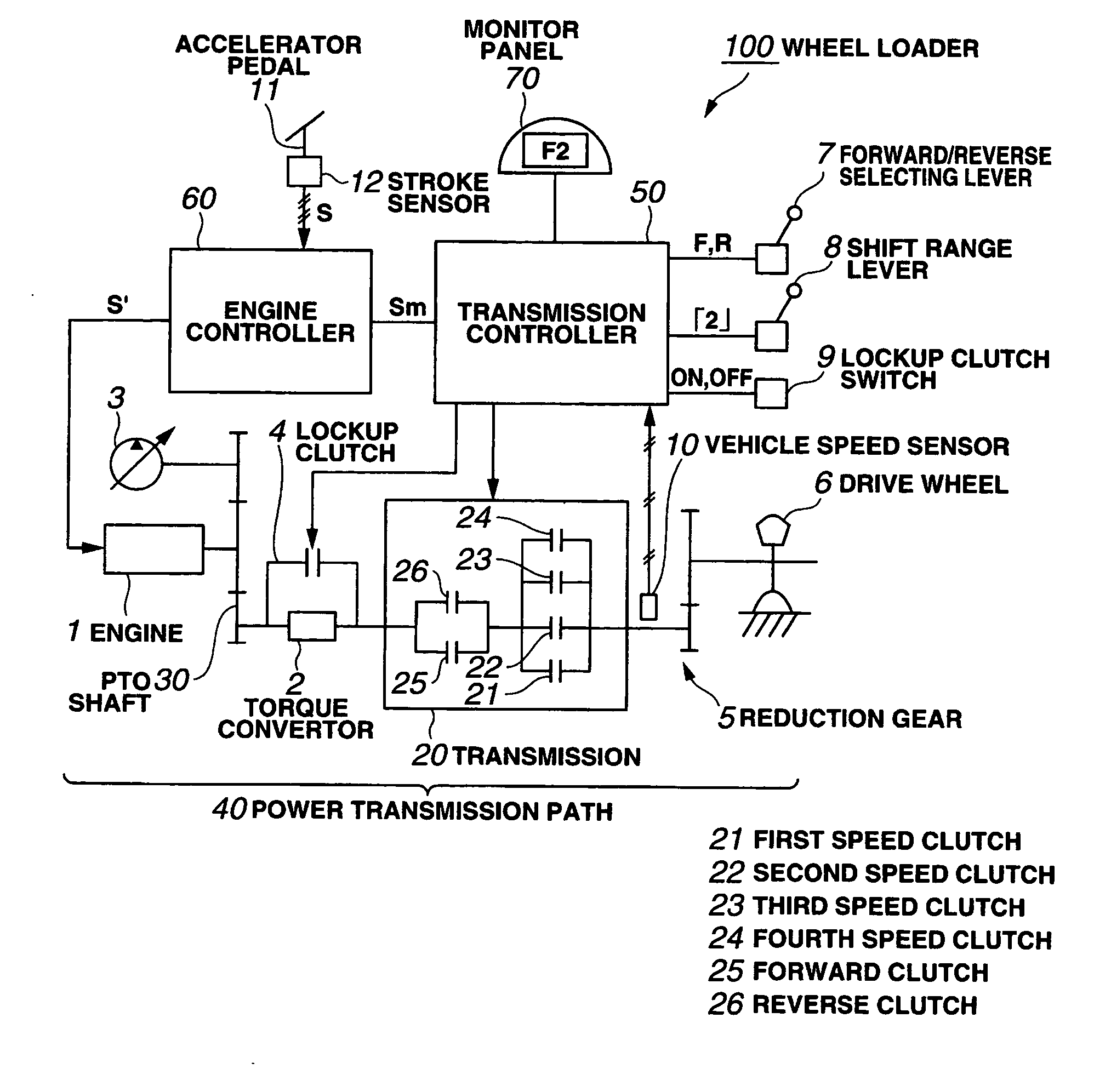
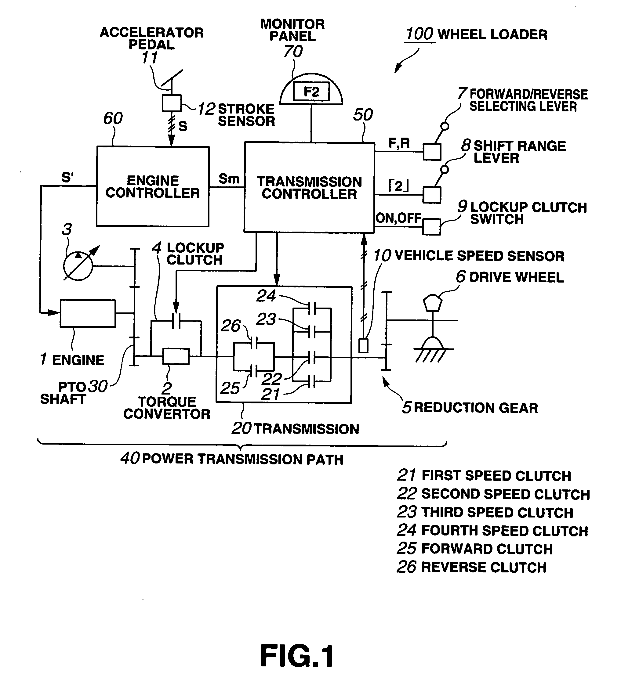
[0037]FIG. 1 is a block diagram of a structure of an engine revolutions control device of a working vehicle according to an embodiment, showing portions according to the present invention in connection with a structure of a wheel loader.

[0038]As shown in FIG. 1, a power transmission path 40 of the engine 1 of the wheel loader 100 is provided with a transmission 20 which has a first speed clutch 21, a second speed clutch 22, a third speed clutch 23 and a fourth speed clutch 24 which correspond to a forward clutch 25 corresponding to a forward running gear, a reverse clutch 26 corresponding to a reverse running gear, speed gear clutches corresponding to individual speed gears, namely a first speed gear, a second speed gear, a third speed gear and a fourth speed gear. Each clutch is configured of a wet-type multi-plate hydraulic clutch.

[0039]The output shaft of the engine 1 of the wheel loader ...


PUM


Abstract

To provide an engine revolutions control device of a working vehicle that the braking effect can be obtained by the low-speed speed gear as expected by the operator at the time of forward / reverse changeover and the durability of the clutch can be enhanced without increasing the capacity of the clutch. When the low-speed gear change range suitable for the work is selected by the shift range lever and the speed gear clutch corresponding to the maximum speed gear of the selected gear change range in the individual speed gear clutches is engaged, the throttle amount upper limit value which limits the revolutions of the engine so to have the upper limit vehicle speed or less corresponding to the maximum speed gear is determined, and it is output as a throttle amount correction command signal to an engine controller. The engine controller compares the content of the throttle correction command signal input from the transmission controller, namely the throttle amount upper limit value with a throttle amount as a depressing operation amount of the accelerator pedal, generates as the corrected throttle amount the smaller throttle amount and controls the engine 1 so that the target revolutions according to the corrected throttle amount can be obtained.

Description

TECHNICAL FIELD[0001]The present invention relates to a working vehicle which is moved as its engine power is transmitted to the transmission, and more particularly to an apparatus and method of controlling engine revolutions.BACKGROUND ART[0002]A power transmission path of the engine of a wheel loader is provided with a transmission having a forward clutch, a reverse clutch, and respective speed gear clutches.[0003]For example, when a working vehicle is moving backward and a forward / reverse selecting lever which is provided at a driver seat is operated to a forward position, a gear change command is generated, the forward clutch is selected, switching is made from the reverse clutch before the gear change to the selected forward clutch after the gear change, the engine power is transmitted to the selected gear-changed forward clutch of the transmission to drive the drive wheels, and the vehicle is changed to move from reverse to forward.[0004]The wheel loader often performs V-shape...

Claims


Application Information

Patent Timeline
Patent Type & Authority Applications(United States)
IPC IPC(8): B60W10/04F16H61/14B60W30/18F02D29/00F16H59/08F16H61/02F16H61/68F16H61/684F16H63/50
CPCB60W30/1846B60W30/186B60W50/087F02D29/00F16H35/10Y10T477/6352F16H63/50Y10T477/68Y10T477/679Y10T477/63385F16H61/682B60K31/00F16H61/02
Inventor HATANAKA, YASUSHI
Owner KOMATSU LTD
Why Eureka
Try Eureka