Ultrasonic diagnosis system and pump apparatus

a technology which is applied in the field of ultrasound diagnosis system and pump apparatus, can solve the problems of high complexity of technique, damage to tissue surface of body cavity, and low operability of the construction of conduit operation, so as to facilitate flow instruction and reliably operate for inflation

Inactive Publication Date: 2009-10-01
FUJIFILM CORP
View PDF6 Cites 37 Cited by
  • Summary
  • Abstract
  • Description
  • Claims
  • Application Information

AI Technical Summary

Benefits of technology

[0025]Accordingly, the balloon at an end of an ultrasonic endoscope can operate reliably for inflation and deflation, because the inflation and deflation input devices are effective in easily instructing the flow of the transmission medium into or out of the balloon.

Problems solved by technology

A problem of high complexity arises in the technique disclosed in this document.
However, the physician must operate a switch on a pump body which is installed separately, so that operability of the construction for operating the conduits is not higher.
If the physician carries out the inflation and deflation of the balloon, it is likely to damage the tissue surface of the body cavity with an error in operation of the switch, because he or she must gaze the switch in place of viewing a display panel displaying an ultrasonic or endoscopic image.
However, an error in operation of the foot switch is likely to occur specifically because a plurality of the foot switches are used additionally in connection with other medical instruments.
However, the conduits for supply of air and water have a complicated structure in which valves change over the conduits between open and closed states.
Applied use of the conduits of supply of air and water for the inflation and deflation of the balloon causes a problem of higher complexity in the structure, because the numbers of the valves and the conduits increase.
The structural complexity will lower the reliability, because jamming is more likely to occur in the conduits.

Method used


Image

  • Ultrasonic diagnosis system and pump apparatus
  • Ultrasonic diagnosis system and pump apparatus
  • Ultrasonic diagnosis system and pump apparatus

Examples


Embodiment Construction

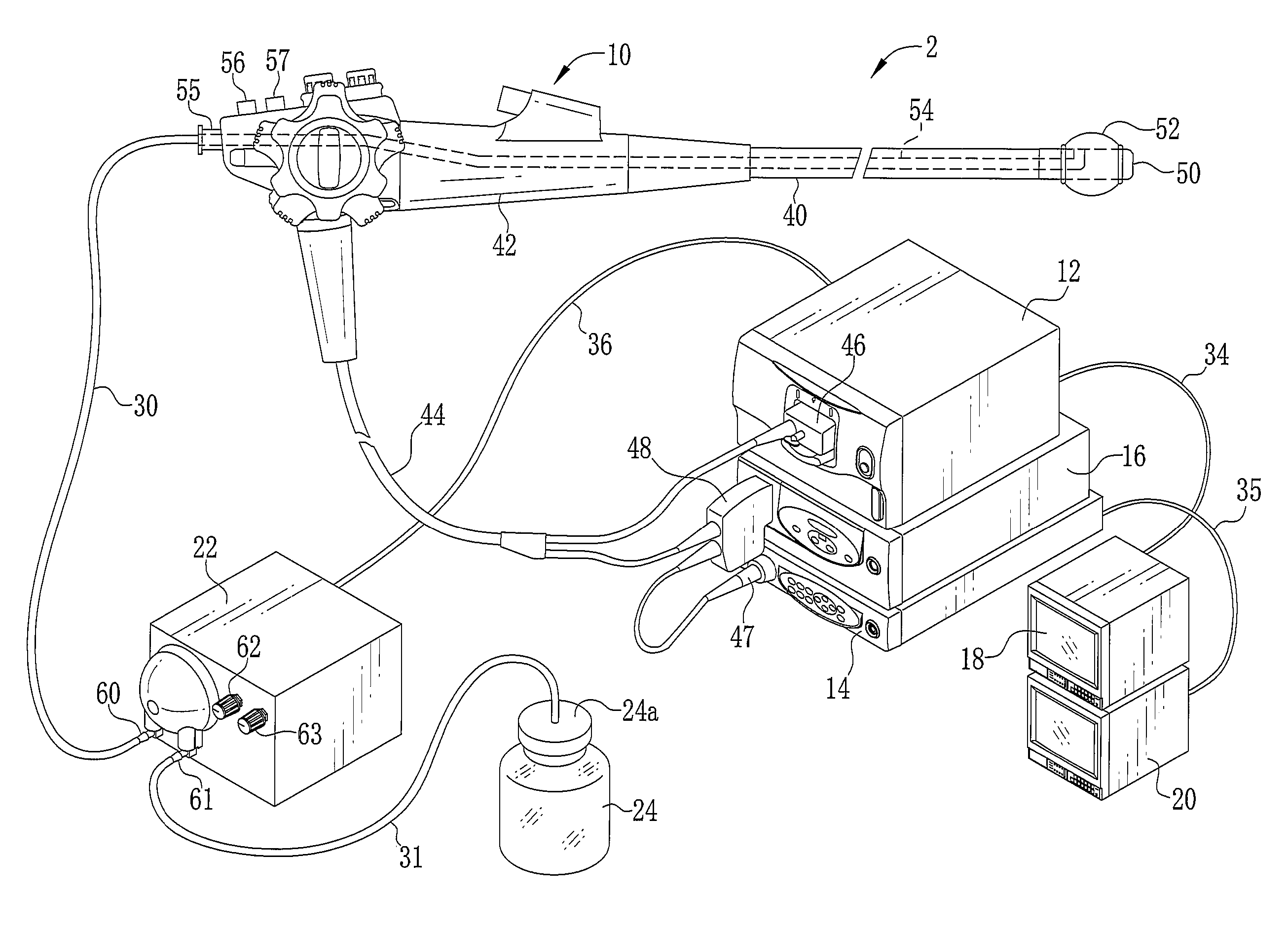
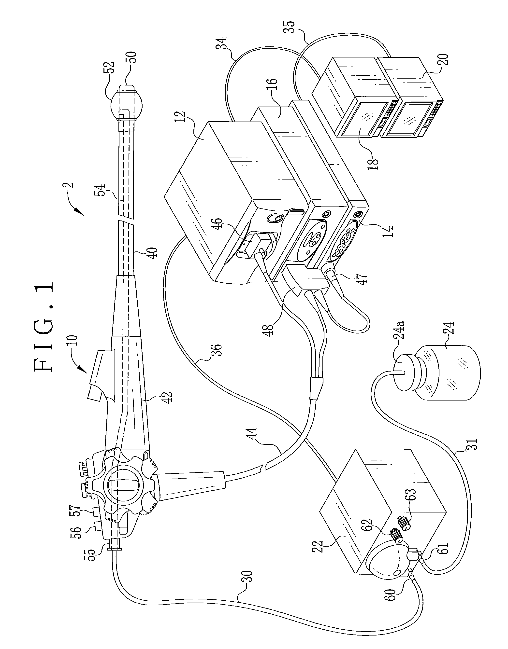
[0041]In FIG. 1, an ultrasonic diagnosis system 2 includes an ultrasonic endoscope 10, an ultrasonic processor 12, an endoscope processor 14, a light source unit 16, an ultrasonic monitor display panel 18, an endoscope monitor display panel 20, a pump apparatus 22, and a water tank 24 as water source. The ultrasonic endoscope 10 picks up an image of an object in a body cavity or gastrointestinal tract. The ultrasonic processor 12 creates an ultrasonic image. The endoscope processor 14 creates an endoscopic image. The light source unit 16 generates illumination light for illuminating the object. The ultrasonic monitor display panel 18 displays the ultrasonic image. The endoscope monitor display panel 20 displays the endoscopic image. The pump apparatus 22 causes water to flow into and out of the ultrasonic endoscope 10. The water tank 24 stores the water in connection with the pump apparatus 22.

[0042]The ultrasonic endoscope 10 includes an insertion tube 40, a handle 42 and a univers...


PUM


Abstract

An ultrasonic endoscope has an ultrasonic transducer for emitting and receiving ultrasonic waves, a balloon support, having the ultrasonic transducer, for supporting a balloon mounted thereon to cover the ultrasonic transducer hermetically and removably. In an ultrasonic diagnosis system, the ultrasonic endoscope includes an inflation button adapted to inflating the balloon. A deflation button is adapted to deflating the balloon. Furthermore, a flow line extends to the balloon to pass water. A pump apparatus includes a rotary pump for drawing the water through the flow line, to cause the water to flow into and out of the balloon. A pump controller controls the rotary pump, inflates the balloon by supplying the water in response to an inflation signal from the inflation button, and deflates the balloon by discharging the water in response to a deflation signal from the deflation button.

Description

BACKGROUND OF THE INVENTION[0001]1. Field of the Invention[0002]The present invention relates to an ultrasonic diagnosis system and pump apparatus. More particularly, the present invention relates to an ultrasonic diagnosis system and pump apparatus in which a balloon at an end of an ultrasonic endoscope can operate reliably for inflation and deflation.[0003]2. Description Related to the Prior Art[0004]Ultrasonic diagnosis in the medical field is a non-invasive diagnosis for applying ultrasonic waves to an object in a patient's body, to observe a state of the object by receiving and imaging echo ultrasonically reflected from the object. An example of ultrasonic diagnosis is in-vivo diagnosis for applying the ultrasonic waves upon entry of a probe in a body cavity. It is possible in the in-vivo diagnosis to examine the tissue of the body cavity or gastrointestinal tract more precisely than in extracorporeal device diagnosis with the ultrasonic waves. The in-vivo diagnosis is importan...

Claims


Application Information

Patent Timeline
Patent Type & Authority Applications(United States)
IPC IPC(8): A61B8/14A61B1/00
CPCA61B1/00082A61B1/00101A61B8/445A61B8/12A61B8/582A61B1/015
Inventor NARUSE, MUTSUMIYOSHIHARA, MASATOSHI
Owner FUJIFILM CORP
Why Eureka
Try Eureka