Wireless Implantable Medical Device

a medical device and implantable technology, applied in the direction of antenna feed intermediates, elongated active elements, structural forms of radiation elements, etc., can solve the problems of limited functionality between the implantable medical device and the external unit, the integration of the antenna in such small implantable devices, and the patient's mobility is reduced, etc., to achieve low loss, low dielectric constant, and low loss

Active Publication Date: 2009-10-01
FRACTUS
View PDF3 Cites 82 Cited by
  • Summary
  • Abstract
  • Description
  • Claims
  • Application Information

AI Technical Summary

Benefits of technology

[0028]Therefore, in certain cases, it can be advantageous to provide insulation between an antenna integrated in the wireless implantable medical device and the body tissues surrounding said device. In general it will be advantageous to insulate from the body tissues with high ohmic losses those parts of the antenna and / or the implantable medical device in which the surface currents induced by the operation of the antenna are strong.
[0029]In some embodiments, insulation is obtained by creating a cavity within the dielectric compartment (such as a plastic header) that encompasses at least a portion of the antenna. The said cavity can encompass partially or completely said at least a portion of the antenna that is located within the dielectric compartment. In some cases, the cavity can be substantially empty (i.e., vacuum is created in it) while in other cases the cavity can be partially or completely filled with a biocompatible material with low dielectric losses and / or low dielectric constant.
[0030]In some other embodiments, enhanced insulation between the wireless implantable medical device and the surrounding body tissues can be obtained by partially or totally coating the region of the device containing the antenna with a layer of biocompatible dielectric material with low losses and / or low dielectric constant. In some cases, the device housing itself will be partially or completely coated with a biocompatible dielectric material with low dielectric losses and / or low dielectric constant. Coating at least a portion of the wireless implantable medical device with a layer of biocompatible dielectric material with low dielectric losses and / or low dielectric constant is in some cases preferable to creating a cavity within the dielectric compartment of the device due to its lower mechanical complexity.

Problems solved by technology

One of the problems of this technique is that, as the near-fields decay very rapidly with distance, the external antenna (typically a loop antenna) has to be placed within a few centimeters from the implanted device in order for the communication to take place, which is inconvenient for a clinician, reduces the mobility of the patient, and allows limited functionality between the implantable medical device and the external unit.
However, an important problem of this approach is the integration of an antenna in such small implantable devices, as the space required for an antenna to operate at the frequency bands typically used for medical applications is large compared to the dimensions of these devices.
Furthermore, attempts to make small antennas have resulted in these antennas being very inefficient, which leads to a decreased range, an increase in power consumption and, therefore, to shorter battery life.

Method used


Image

  • Wireless Implantable Medical Device
  • Wireless Implantable Medical Device
  • Wireless Implantable Medical Device

Examples


Embodiment Construction

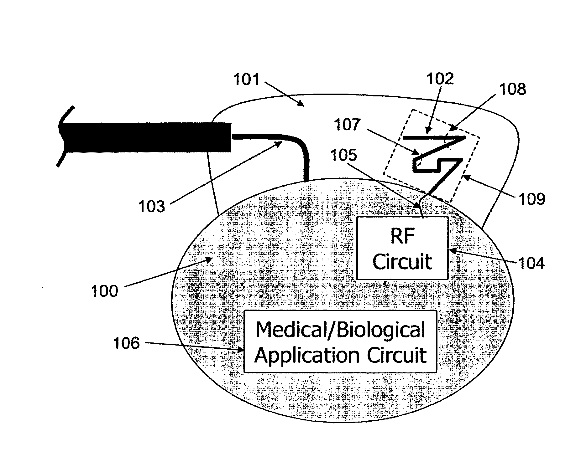
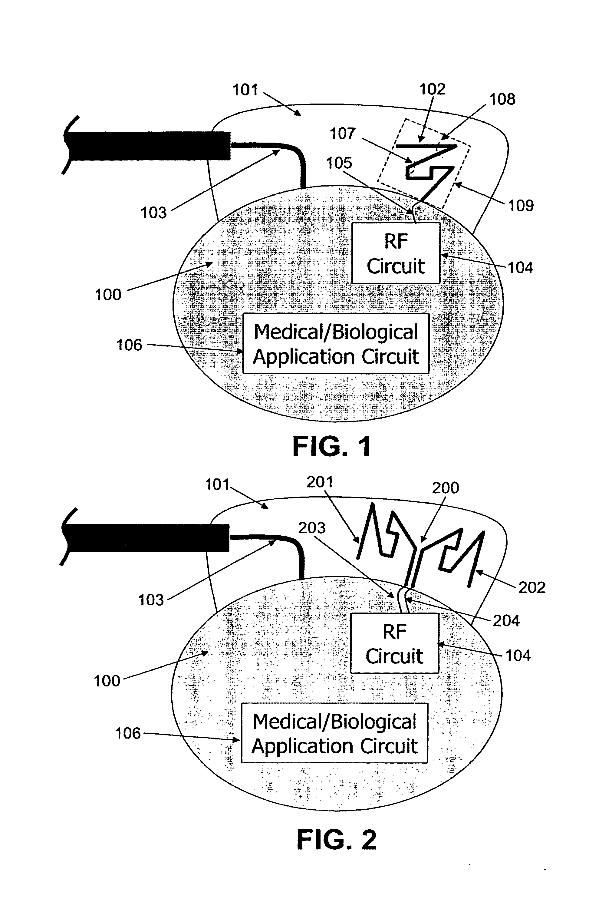
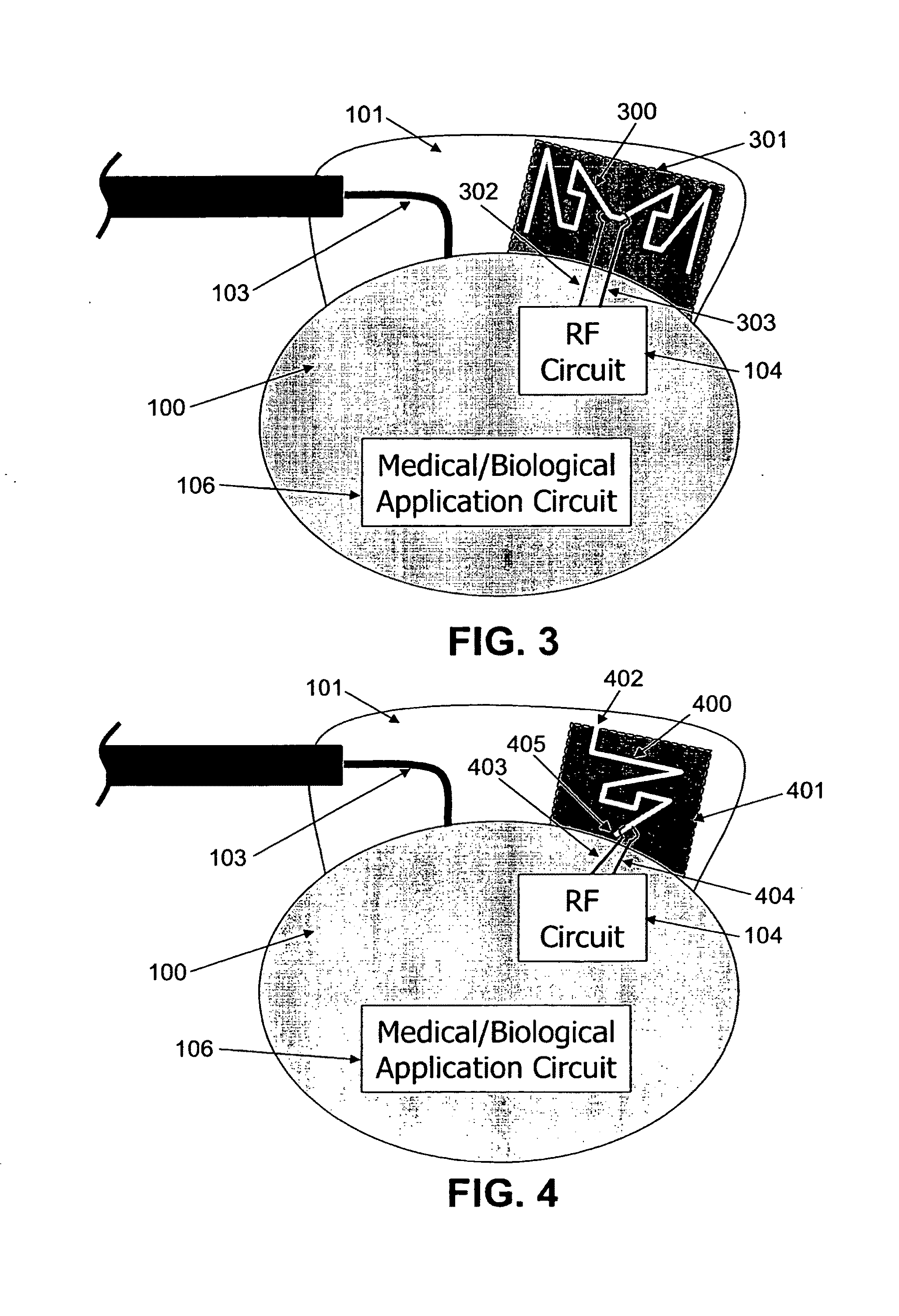
[0061]In accordance with some embodiments of the invention, the implantable medical device comprises: a device housing, a radio frequency (RF) circuit, an electronic circuit that provides a medical or biological function (such as for instance cardiac rhythm management in the case of a pacemaker), a power source (such as a battery), an antenna, a dielectric compartment (such as for instance a plastic header) that encompasses at least a portion of the antenna, and at least one terminal to electromagnetically couple the antenna to the RF circuit. The housing of the device is usually made of a biocompatible metal or alloy (such as for instance titanium), which has the property of shielding the inside electronics from the outside radiations. In some embodiments, the housing can also implement other functions, or have different uses, such as for example an electrode to deliver electrical pulses, or discharges. In some preferred embodiments, the antenna comprises a conducting pattern, at l...


PUM


Abstract

One aspect of the invention relates to an implantable medical device comprising a device housing (100), at least one radio frequency circuit (104) for radio frequency communication, at least one antenna, at least one terminal to electromagnetically couple said at least one antenna to said at least one radio frequency circuit, and a dielectric compartment (101, 1661) that encompasses at least a portion of said at least one antenna. The antenna comprises a conducting pattern, at least a portion of which is shaped as a curve, wherein said curve comprises at least five segments, wherein each of said at least five segments forms an angle with each adjacent segment in said curve, wherein at least three of the at least five segments of said curve are shorter than one-fifth of the longest free-space operating wavelength of the antenna, wherein each angle between adjacent segments is less than 180°, and at least two of the angles between adjacent sections are less than approximately 115°.

Description

OBJECT AND BACKGROUND OF THE INVENTION[0001]The present invention relates generally to novel implantable medical devices that include a new family of miniature antennas in the device. Also, the invention relates to several novel ways of arranging said miniature antennas inside implantable medical devices, and novel wireless communication systems comprising implantable medical devices with an integrated antenna.[0002]Implantable medical devices (such as for instance cochlear implants, hearing devices, neuro-stimulators, cardioverter defibrillators, congestive heart failure devices, pacemakers, ventricular assist devices, artificial hearts, insulin pumps, drug pumps, incontinence devices, bone growth stimulators, or orthopedic implants) are currently used to treat a medical condition or pathology of a patient (e.g., an insulin pump to treat diabetes), or to overcome an impairment of a physiological functionality (e.g., a cochlear implant to restore the hearing functionality).[0003]The...

Claims


Application Information

Patent Timeline
Patent Type & Authority Applications(United States)
IPC IPC(8): A61N1/08
CPCA61N1/37229A61N1/375H01Q9/42H01Q9/26H01Q1/36A61N1/37512
Inventor MUMBRU, JOSEPSOLER, JORDIPUENTE, CARLES
Owner FRACTUS
Why Eureka
Try Eureka