Acoustically optimized cabin wall element

a cabin wall and acoustic optimization technology, applied in the direction of instruments, transportation and packaging, synthetic resin layered products, etc., can solve the problems of significant and unacceptable addition weight of the overall cabin, poor sound insulation characteristics in relation to engine noise, and measures alone do not achieve the desired good sound reduction characteristics, so as to improve the acoustic absorption capacity of the cabin wall, improve the sound insulation, and improve the effect of cabin wall acoustic absorption

Active Publication Date: 2009-10-08
AIRBUS OPERATIONS GMBH
View PDF16 Cites 74 Cited by
  • Summary
  • Abstract
  • Description
  • Claims
  • Application Information

AI Technical Summary

Benefits of technology

[0008]A wall element according to the present invention, comprising the characteristics stated in claim 1, provides for an improved efficiency of a cabin as a sound-reducing element of a transport means, in particular in relation to the lower frequency range below SOD Hz, without increasing the weight of the aircraft wall structure or the lining elements.
[0009]In the basic design of the sandwich element according to the invention two different measures for reducing the sound that acts on a cabin are combined. The sandwich element according to the invention comprises a core layer which preferably comprises a collection of honeycomb cells that are separated from each other by walls. In order to improve the rigidity of the core layer, on one side a first cover layer and on the other side a second cover layer are arranged, of which at least the first cover layer or the second cover layer comprises microperforation. Microperforation makes possible an acoustic interaction between the air that surrounds the sandwich element according to the invention and the hollow spaces of the honeycomb cells of the core layer so that as a first sound insulating measure sound may be absorbed.
[0011]Preferably, the sandwich element according to the invention comprises a microperforated cover foil or film, at least on one side, which cover foil or film comprises perforation holes with a diameter of max. 1 mm, or in an advantageous improvement of max. 0.5 mm, which perforation holes make it possible to achieve an improved sound absorption effect.
[0013]In a further advantageous embodiment of the invention, the acoustic absorption of a cabin wall may be further improved by integrated wall elements, comprising a lining element and glass wool layers with microperforated absorber areas. Such an arrangement could be designed as a compact single-part element in which an insulation packet is located between the sandwich element according to the invention and a microperforated film or foil.
[0014]In a further embodiment of the invention, a multilayer design with glass wool layers and microperforated absorber areas that are situated in between may be used in order to further improve the acoustic absorption capacity of the cabin wall that is lined with sandwich elements according to the invention. Thus as a result of the multilayer design of different glass wool layers and the microperforated absorber areas situated in between, jumps in impedance between the individual layers occur. This results in multiple reflection, transmission and absorption of the sound waves that enter from the outside, wherein a clear improvement in sound insulation takes place.

Problems solved by technology

However, these measures by themselves do not achieve the desired good sound-reduction characteristics in particular in the frequency range below 500 Hz.
Up to now only additional specific weight has been effective in this context, which weight has to be applied, in a sheet-like manner as mass, to the primary structure or to the cabin wall elements, and overall has resulted in significant and unacceptable additional weight of the overall cabin.
There is a particular need for improved sound insulation in this frequency range if the fuselage is made from CRP, because a CRP fuselage, in particular in the low frequency range, generally below 500 Hz, has particularly poor sound-insulating characteristics in relation to engine noise.

Method used


Image

  • Acoustically optimized cabin wall element
  • Acoustically optimized cabin wall element
  • Acoustically optimized cabin wall element

Examples


Embodiment Construction

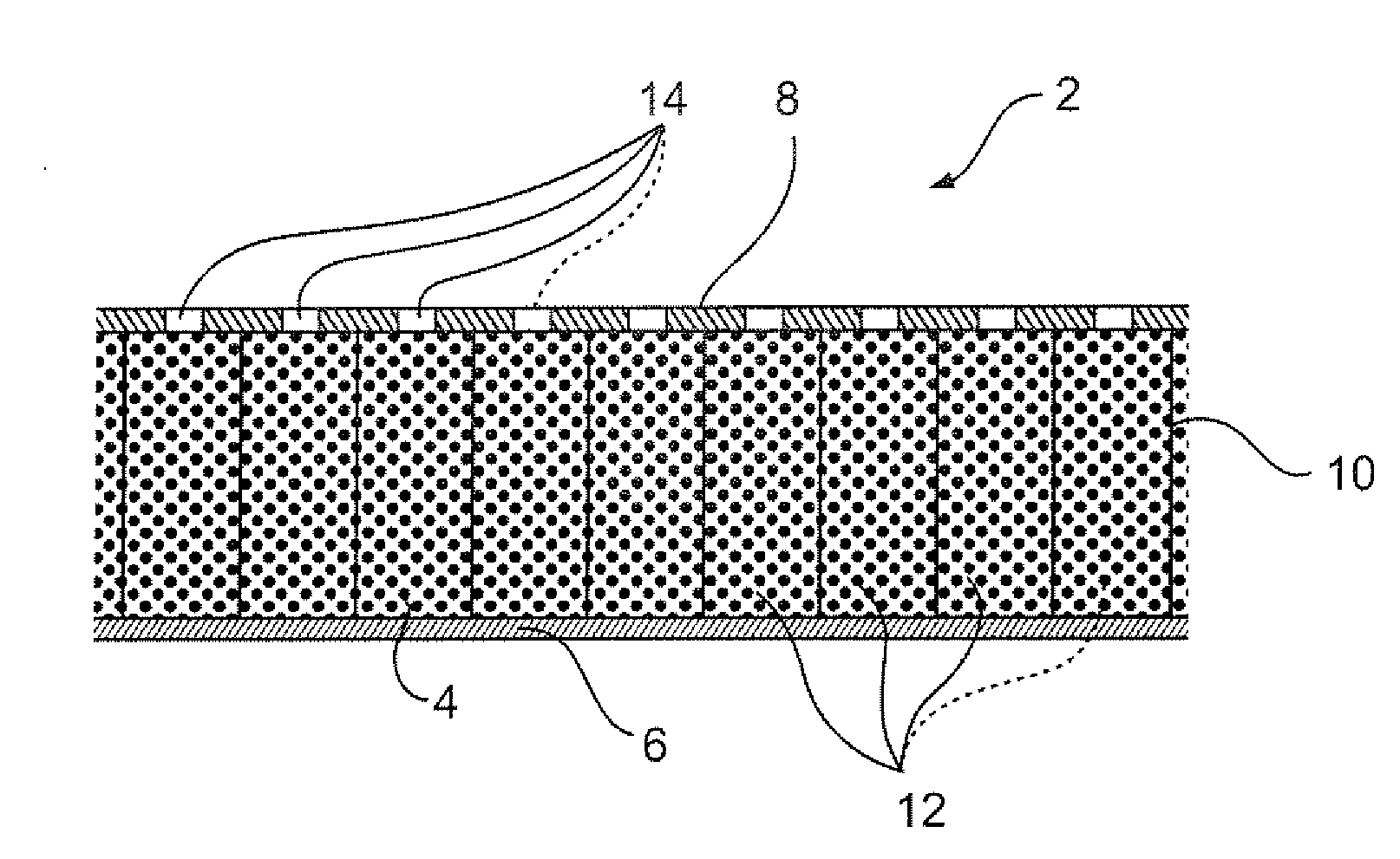
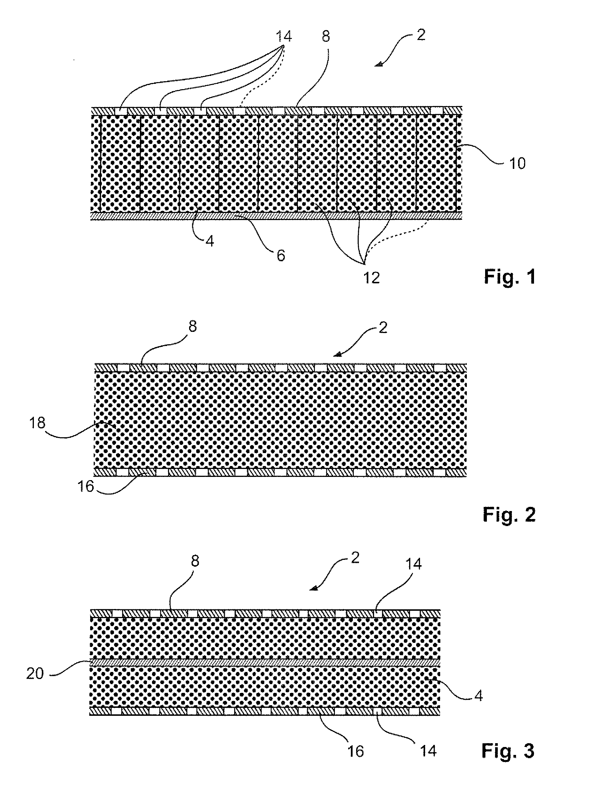
[0023]FIG. 1 shows a simple basic design of the sandwich element 2 according to the invention, which sandwich element 2 comprises a honeycomb core 4, a bottom cover layer 6 and a top cover layer 8. In this example the core layer 4 is designed as a honeycomb structure, which for improved sound absorption could additionally comprise sound-absorbent material. This material could, for example, be open-pore or open-cell material, e.g. glass wool or foam material that has been placed between the walls 10 of the individual honeycomb cells 12, wherein the glass wool may, for example, have been placed into the honeycomb 12, either pressed in the form of a non-woven glass fabric with a high binding-agent content, or non-pressed.

[0024]The material of the walls 10 of the honeycomb cells 12 could be made from an aramide fibre material, in particular a meta-aramide material; a semi-finished product that is also known by the name of “Nomex® paper”. Such a honeycomb structure by itself does not pro...


PUM

PropertyMeasurementUnit
diameteraaaaaaaaaa
diameteraaaaaaaaaa
frequencyaaaaaaaaaa

Abstract

A wall element for the sound-insulating interior lining of a transport device, comprising at least one sandwich element, at least one insulation package and at least one absorber plane element. The sandwich element comprises at least one core layer, a first cover layer and a second cover layer, wherein the first cover layer and the second cover layer are each arranged on one side of the core layer. At least the first or the second cover layer is a microperforated layer; the sandwich element possesses a shear rigidity that is adjusted in such a way that the sandwich element comprises one or several coincidence boundary frequencies that are determined by the shear rigidity, which coincidence boundary frequencies are outside the frequency range that dominates the noise in the interior of the cabin; and the shear rigidity of the sandwich element at the same time is sufficient for said sandwich element to be used as an interior lining. Sound-insulating interior lining according to the aspects according to the invention provides adequate sound insulation also in the lower frequency range of below 500 Hz, without increasing the weight of the interior lining when compared to the weight of conventional interior linings.

Description

CROSS-REFERENCE TO RELATED APPLICATIONS[0001]This application claims the benefit of the filing date of U.S. Provisional Patent Application No. 61 / 123,011 filed Apr. 4, 2008, the disclosure of which application is hereby incorporated herein by reference.[0002]The invention relates to a sandwich element for the sound-insulating interior lining of a transport means.BACKGROUND OF THE INVENTION[0003]Such sound-insulating interior linings increase the wellbeing of passengers traveling in the cabin of a transport means. In particular, cabins of commercial aircraft are exposed to a number of loud external noise sources, for example engine noise and noise of turbulent boundary-layer flow. The acoustic insulation of aircraft cabins using passive measures is confronted by new challenges as a result of the introduction of aircraft fuselages constructed from carbon-fibre reinforced plastic (CRP), because such fuselages, due to their lighter specific weight and greater rigidity, when compared to ...

Claims


Application Information

Patent Timeline
Patent Type & Authority Applications(United States)
IPC IPC(8): E04B1/82
CPCB32B3/26G10K11/168B64C1/40B60R13/0815B32B5/024B32B5/18B32B5/245B32B5/26B32B27/065B32B27/12B32B27/18B32B3/12B32B3/266B32B2260/021B32B2260/046B32B2262/0269B32B2262/101B32B2262/106B32B2307/102B32B2307/51B32B2307/542B32B2307/718B32B2307/734B32B2605/18
Inventor GLEINE, WOLFGANGTHOMAS, CHRISTIAN
Owner AIRBUS OPERATIONS GMBH
Why Eureka
Try Eureka