
Holster for charging pectorally-implanted medical devices

Inactive Publication Date: 2009-10-08
MEDTRONIC INC
View PDF8 Cites 19 Cited by
  • Summary
  • Abstract
  • Description
  • Claims
  • Application Information

AI Technical Summary

Benefits of technology

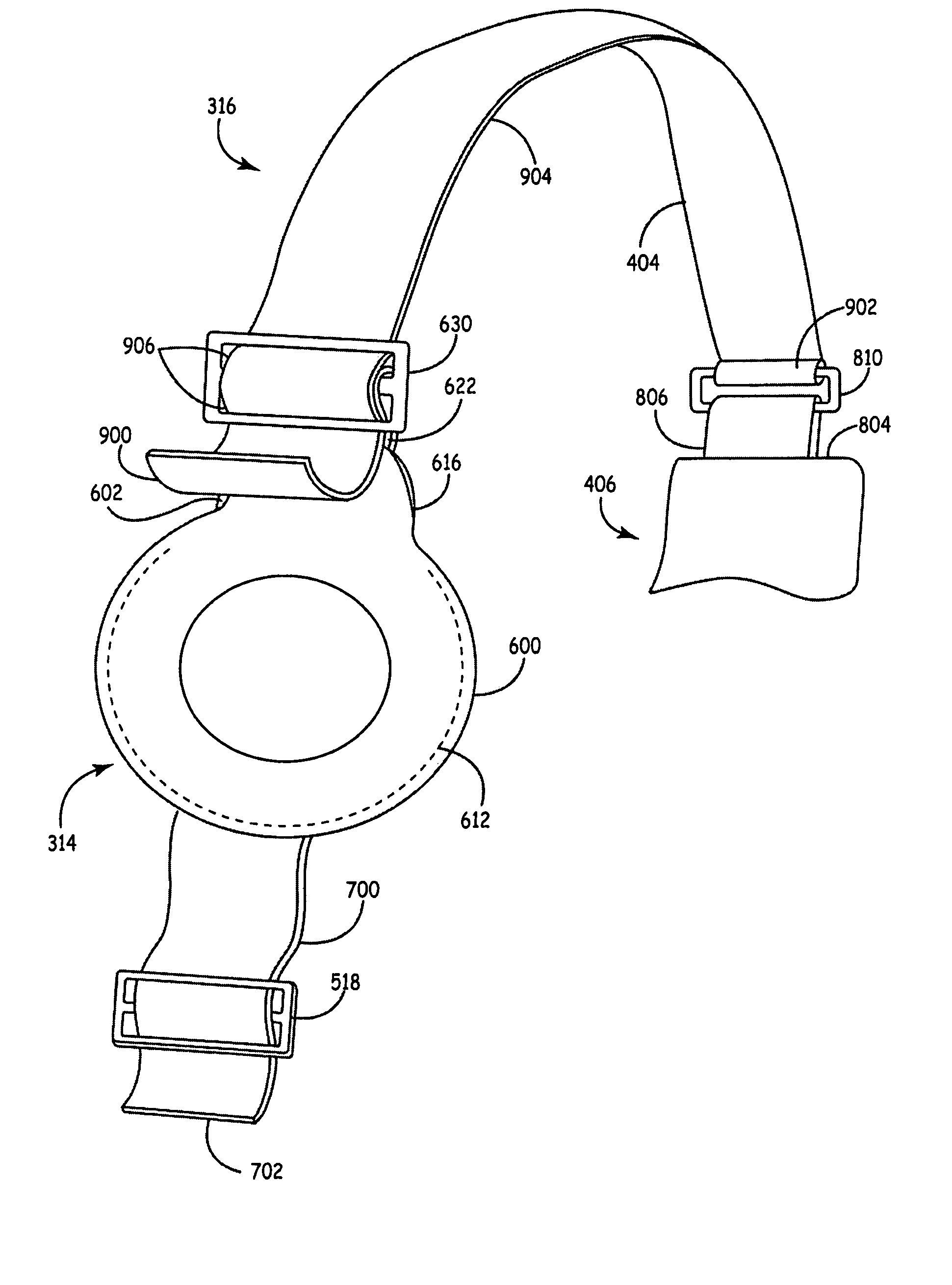
[0016]The shoulder strap includes first and second ends that are adapted to engage the torso strap. At least one of these ends is selectively positionable at any point along the intermediate portion of the torso strap that is not otherwise occupied by the other end of the shoulder strap. As an example, in one embodiment, the second end of the shoulder strap may be selectively positioned at any point along the intermediate portion of the torso strap that is not otherwise occupied by the first end of the shoulder strap. In another embodiment, the first end of the shoulder strap may be selectively positioned at any point along the intermediate portion of the torso strap not otherwise occupied by the second end. In yet another embodiment, each of the first and second ends may be selectively positioned to occupy any selected point along the intermediate portion of the torso strap not otherwise occupied by the other end. The foregoing types of adjustments may be made with, or without, the first and second ends of the torso strap coupled together. This high degree of adjustability allows the holder of the holster to be readily positioned at an optimal location in the vicinity of a pectorally-implanted IMD. This provides for maximum recharge efficiency and a decrease in recharge time.
[0018]In another embodiment, the shoulder strap further includes a front portion, and the holder may be coupled to, or include, a strap. The strap of the holder may be adjusted relative to the front portion of the shoulder strap. This allows the patient to select the height at which the torso strap encircles his torso, and provides for greater patient comfort.
[0019]According to another aspect of the invention, the shoulder strap may include a vest to encircle at least a portion of the patient's back. The vest may be padded to enhance patient comfort.
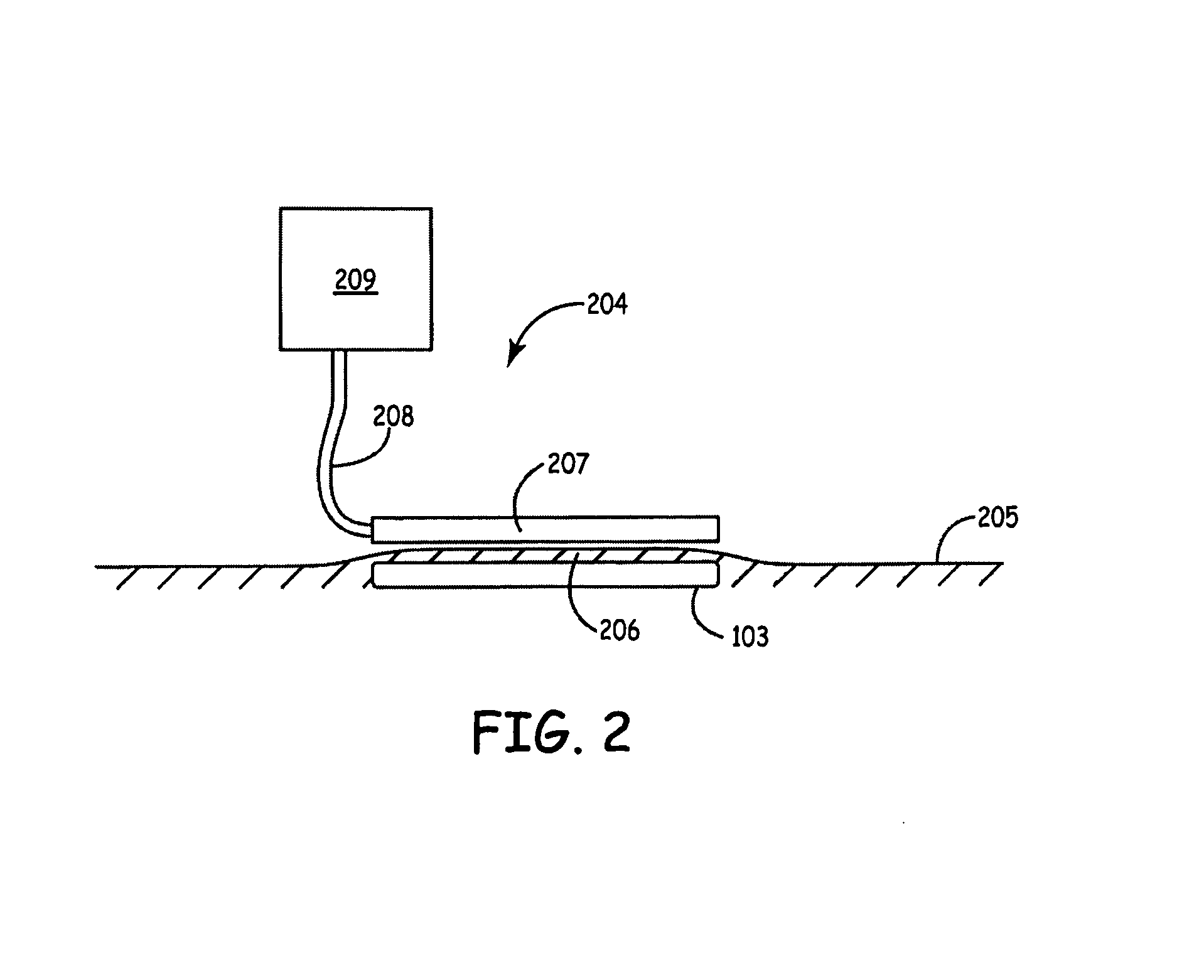
[0020]The invention may further include a holder to carry the external charging unit. This holder may include a clip that couples to a support structure such as the torso strap, a belt worn by the patient, a pocket of the patient's clothing, or any other similar structure. This allows the external charging unit to be conveniently supported when the antenna is positioned within the holder of the shoulder strap.

Problems solved by technology

However, having electrical wires that perforate the skin is disadvantageous due, in part, to the risk of infection.
Further, continuously coupling patients to an external Power source for therapy is a large inconvenience.
However, such single cell batteries usually do not supply the lasting power required to perform therapies provided by newer IMDs.
First, the inductive coupling has a tendency to heat surrounding components and tissue.
Since it is desirable to limit this heating effect, the amount of energy transfer per unit time must also be limited.
This attachment may impair the patient's mobility and limit the patient's comfort.
Finally, the amount of energy available to the IMD may be limited by the amount of time the patient is willing to devote to recharging the device.

Method used


Image

  • Holster for charging pectorally-implanted medical devices
  • Holster for charging pectorally-implanted medical devices
  • Holster for charging pectorally-implanted medical devices

Examples


Embodiment Construction

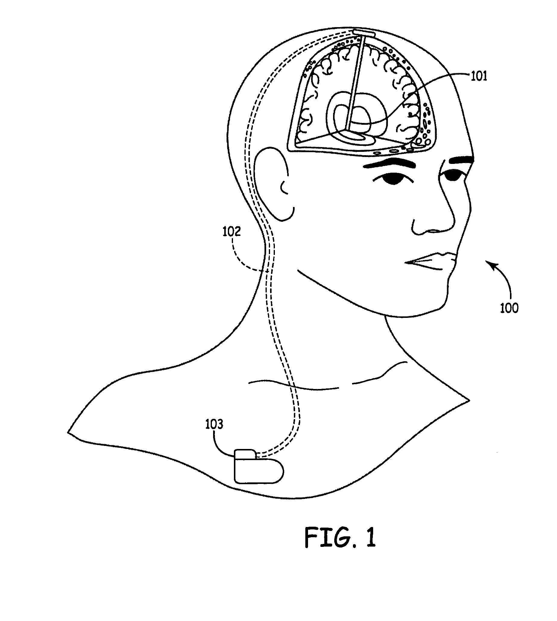
[0048]The current invention relates to a holster for charging pectorally-implanted Implantable Medical Devices (IMDs). The term “charge” refers to any type of charge including, but not limited to, an initial charge and a recharge. The pectoral region is preferably proximate the pectoral muscles and is more preferably within a region of the body below the clavicle, above the xiphoid process of the sternum, and between the sternum and the axilla, which is a cavity beneath the junction of the arm and the torso. An example of a suitable pectorally-implanted medical device for use with the present invention is disclosed in U.S. Patent Publication No. US 2005 / 0245996 A1, published Nov. 3, 2005, entitled “Spacers for Use with Transcutaneous Energy Transfer System”.

[0049]One embodiment of the holster includes a torso strap and shoulder strap. The torso strap includes first and second ends and an intermediate portion there between. The first and second ends of the torso strap are adapted to ...


PUM


Abstract

A holster that may be donned for charging a pectorally-implanted implantable medical device (IMD) on the patient's right or left side. The holster includes a torso strap that encircles a patient's torso. The torso strap includes first and second ends and an intermediate portion there between. A shoulder strap is provided that extends over either the right or left shoulder of a patient. The shoulder strap includes a holder to house at least an antenna portion of an external charging device used to charge the IMD. The shoulder strap includes first and second ends, at least one of which may be selectably positioned at any point along the intermediate portion of the torso strap to maintain the antenna of the recharger in close proximity to the IMD to reduce charge times.

Description

RELATED APPLICATIONS[0001]The present application includes some subject matter in common with the following co-pending applications, all of which are assigned to the assignee of the present application: U.S. patent application Ser. No. 11 / 741,038 filed Apr. 27, 2007, entitled “Holster for Charging Pectorally Implanted Medical Devices” which is a continuation-in-part of U.S. patent application Ser. No. 11 / 414,155 filed Apr. 28, 2006, entitled “Holster for Charging Pectorally Implanted Medical Devices”.FIELD OF THE INVENTION[0002]The present invention relates to a holster for charging pectorally-implanted medical devices.BACKGROUND OF THE INVENTION[0003]Implantable Medical Devices (IMDs) for producing a therapeutic result in a patient are well known. For example, implantable neurostimulators are available for the treatment of pain, movement disorders such as Parkinson's disease, essential tremor, dystonia, gastric disorders, incontinence, sexual disfunction, and other conditions. Othe...

Claims


Application Information

Patent Timeline
IPC IPC(8): H02J7/00A45F3/02
CPCA61M5/14276A61M2205/8243H02J7/025A61N1/08A61N1/3787A61M2209/088H02J7/0042H02J50/005H02J50/10H02J2310/23
Inventor PHILLIPS, WILLIAM C.SAHASRABUDHE, RAJEEV M.
Owner MEDTRONIC INC
Learn More