Electronic data communication systems

a communication system and electronic data technology, applied in the field of electronic data communication systems, can solve the problems of reducing the system capacity measured in bits/s/hz, interfering between both sessions, and preventing the application of multiple-input-multiple-out (mimo) capacity measures, so as to increase the capacity of an electronic data communication system and increase the size and weight of mobile devices

Inactive Publication Date: 2009-10-08
KINGS COLLEGE LONDON
View PDF10 Cites 70 Cited by
  • Summary
  • Abstract
  • Description
  • Claims
  • Application Information

AI Technical Summary

Benefits of technology

[0018]It is apparent that there is a need for improved method and apparatus that can increase the capacity of an electronic data communication system, particularly in the downlink direction where data bandwidths are high. Terminals in such systems can be nomadic where terminals can move but generally only communicate whilst stationary, ad-hoc where the number of terminals fluctuates with time (i.e. temporary) networks are formed, or fixed. Such apparatus should also be able to take advantage of space-time codes used over a MIMO or MIMO-like channel, but which does not necessarily increase the size and weight of mobile or remote terminals.
[0019]There is also a need for a method and apparatus that can reduce the effects of terminals in bad channel conditions, and particularly when those terminals are unlikely to move from that position for some time.
[0020]The present invention is based on an insight that the capacity of an electronic data communication system as aforementioned can be enhanced by using the mobile or remote terminals served by one or more control terminals to provide a relaying function of data to other terminals. The terminals that perform relaying are known as “relaying terminals” and the terminals that are the recipients of the relayed data are known as “target terminals”. In some embodiments a terminal can be both a relaying and target terminal simultaneously. Preferably the relaying terminals can be grouped together into groups known as “virtual antenna arrays”. The groups are organised so that there is little or no additional interference in the system. There can be one or more control terminal comprising a mobile terminal (e.g. mobile telephone, portable computer), a base station controller or a radio network controller for example. The invention is particularly advantageous for use in ad-hoc networks where the control terminal is a portable device to which appropriate instructions can be downloaded on request or pre-stored thereon.
[0021]The present invention is also based on the insight that the benefits of MIMO channels can be obtained without requiring more than one antenna in the target terminal.
[0024](b) using the control terminal to instruct the at least two relaying terminals to receive and relay data intended for the at least one target terminal, so that the at least one target terminal can receive data directly from at least one terminal and from the at least two relaying terminals, thereby increasing capacity of the system. In one embodiment data is relayed via the at least two relaying terminals substantially simultaneously, thereby providing at least two paths for data to reach the target terminal via the relaying terminals.

Problems solved by technology

The main problem occurred with such deployment is that the r-MT could not communicate with both, the s-MT and the t-MT, at the same time and thus interrupting the session between both.
It thus diminishes the system capacity measured in bits / s / Hz.
It further prevents the application of multiple-input-multiple-output (MIMO) capacity measures in form of e.g. Space-Time Codes or BLAST-like techniques and also gives rise to problems of billing as the r-MT would incur the charges which were generated for the t-MT.
Such approach is not applicable to ad-hoc networks where a clear up- and downlink does not exist as such and where more than two simultaneous links are required.

Method used


Image

  • Electronic data communication systems
  • Electronic data communication systems
  • Electronic data communication systems

Examples


first embodiment

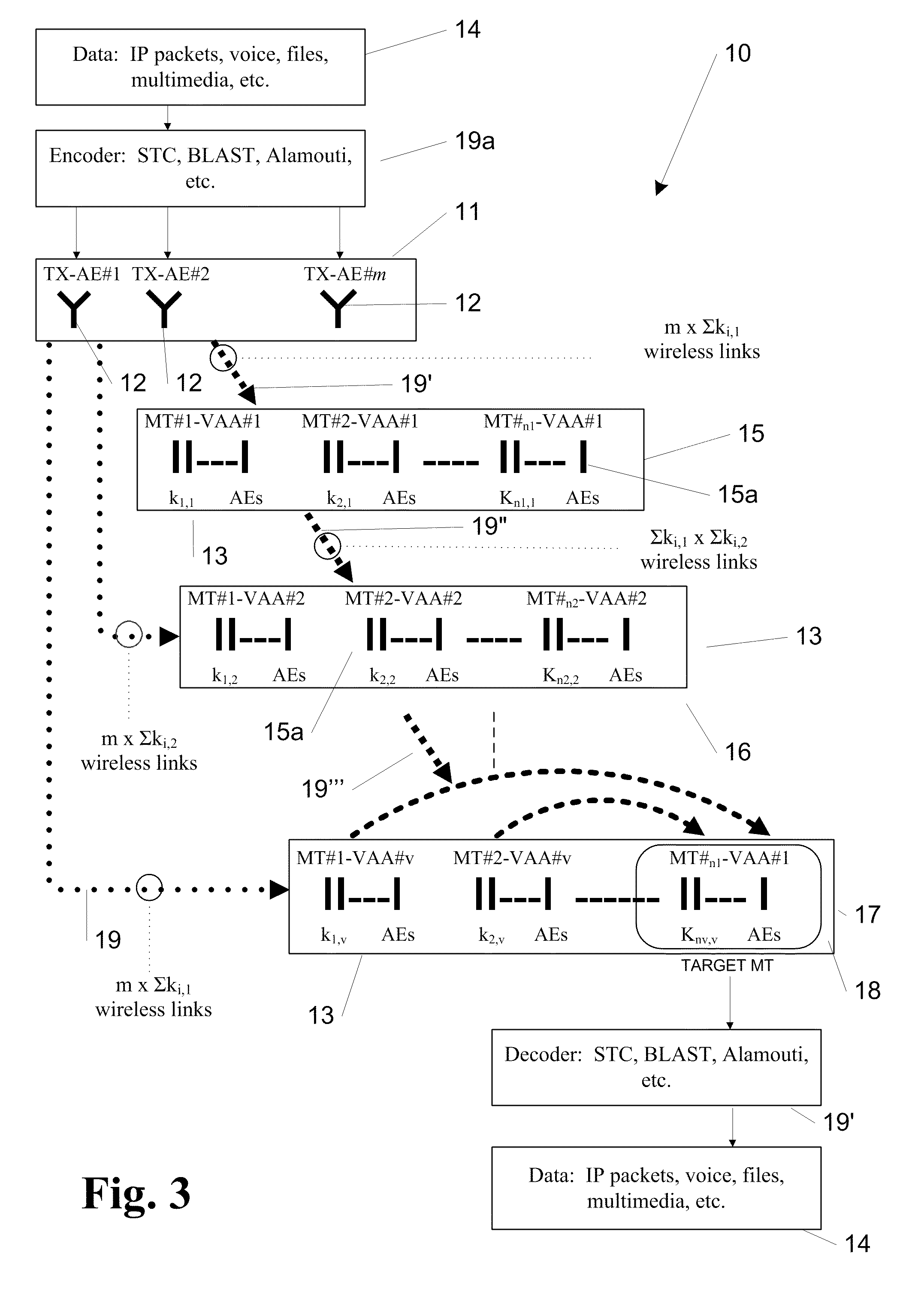
[0080]Referring to FIG. 3 a data communication system is generally identified by reference numeral 10 that comprises a control terminal 11 having m antenna elements 12. The control terminal may be a base station for example. The control terminal 11 is part of a larger network of control terminals (not shown) through which data can be passed. The control terminals serve to divide an area into a number of cells (not shown), as described in the introduction above, permitting inter alia frequency re-use between the cells. There are n1+n2+nv mobile terminals 13 in the cell served by control terminal 11. Referring to FIG. 3A each mobile terminal 13 comprises a RAKE receiver 14a having a plurality of antenna elements 15a, each of which acts as a “finger” that can lock on to uncorrelated copies of the signal created by multipath. The first finger locks on to the strongest signal, the second finger the next strongest and so on. The signal from each finger can be combined by the diversity com...

second embodiment

[0085]Referring to FIG. 4 a data communication system is generally identified by reference numeral 20 that is similar to the data communication system 10 with like numerals indicating like parts. The main difference between the two embodiments is that the data communications system 20 operates in both a downlink and an uplink (mobile terminal to control terminal) mode. One advantage of this is that the power of the t-MT 28 can be reduced leading to less interference in the cell. Another advantage is that whilst the t-MT 28 might be in a fade with respect to the control terminal 21, it is unlikely to be in a fade with respect to the other mobile terminals 13 in the VAAs 25, 26 and 27 such that it can both send and receive data at an improved bit error rate to and from the control terminal 21.

[0086]Referring to FIG. 5 a flowchart showing the main functional requirements of the algorithms required to run a data communication system in the manner described above is generally identified ...

third embodiment

[0122]Referring to FIG. 8 a data communication system is generally identified by reference numeral 60 that comprises a control terminal 61 comprising m antenna elements. There is a plurality of mobile terminals 62 that are part of a VAA 63 that has been set up in accordance with the rules described above. Each mobile terminal 62 is free to move within the cell served by the control terminal 61. The number of mobile terminals 62 is greater than the number of antenna elements of the control terminal. If a mobile terminal 62 moves out of the cell, another control terminal (not shown) will serve it. Each mobile terminal comprises a plurality of antenna 64. In use, data 65 is received from higher layers of the network at the control terminal 61 and appropriately encoded for the transmission scheme in use. The data 65 is transmitted from the control terminal 61 and the mobile terminals receives it and all bar a t-MT 66 re-transmit the data 65 for the benefit of the target mobile 66. The t...


PUM


Abstract

A method of transmitting data across an electronic data communication system comprising a plurality of terminals that can send and receive data in the form of electromagnetic waves to and from at least one of the terminals, which method comprises the steps of: (a) identifying at least one control terminal, at least one target terminal and at least two relaying terminals from the plurality of terminals; and (b) using the control terminal to instruct the at least two relaying terminals to receive and relay data intended for the at least one target terminal, so that the at least one target terminal can receive data directly from at least one terminal and from the at least two relaying terminals, thereby increasing capacity of the system.

Description

FIELD OF THE FIRST INVENTION[0001]The present invention relates to a method, computer program and apparatus for improving the capacity of an electronic data communication system. There is also provided a terminal that can be operated in accordance with the method, and a subscriber identity module card provided with computer executable instructions for carrying out the method.BACKGROUND TO THE INVENTION[0002]Portable electronic devices having the ability to communicate with external networks have become increasingly popular and relatively inexpensive in recent years. Examples of such devices are mobile telephones, notebook computers, pagers and personal digital assistants. Such devices often have the capability of sending and / or receiving data over a wireless link that enables the user to exchange information with other users and / or networks whilst the user remains relatively free to move around. The data can be voice data, text and numerical data, for example, which have been put in...

Claims


Application Information

Patent Timeline
Patent Type & Authority Applications(United States)
IPC IPC(8): H04B7/02H04B7/14H04B1/707H04B7/005H04L12/24H04L12/28H04L12/56
CPCH04B7/2606H04L5/0007H04L5/0032H04L5/0037H04W84/22H04L27/2655H04L41/0893H04W52/46H04L5/0048H04L41/0894
Inventor DOHLER, MISCHAAGHVAMI, ABDOL HAMIDSAID, FATINGHORASHI, SEYED ALI
Owner KINGS COLLEGE LONDON
Why Eureka
Try Eureka