Pyrolysis furnace and process tubes

a technology of process tubes and furnaces, applied in the field of pyrolysis furnaces and process tubes, can solve the problems of reducing the structural life of furnace tubes, reducing reducing the production efficiency of ethylene (ethene) and other olefinic fluids, so as to reduce production and facility downtime, less maintenance, and increase the amount of continuous production runs

Active Publication Date: 2009-10-08
EMISSHIELD
View PDF24 Cites 40 Cited by
  • Summary
  • Abstract
  • Description
  • Claims
  • Application Information

AI Technical Summary

Benefits of technology

[0018]An aspect of the present invention is that the thermal protective layer limits coking; therefore, less maintenance is required, resulting in less downtime, and increasing the amount of continuous production runs possible.
[0019]Another aspect of the present invention is that it generates uniform heating of the refractory walls and process tubes. Uniform heating of the refractory walls results in improved cracking ratios, less maintenance, energy savings and increased production.
[0020]Yet another aspect of the present invention is a dramatic increase in cost efficiently and production. Overall, the cost efficiency and production yields are increased permitting a greater profit and less waste.
[0021]A further aspect of the present invention is that it reduces the outside skin temperature of the furnace.
[0022]Yet a further aspect of the present invention is the increased heat transfer from the furnace refractory walls to the process tubes and the increased thermal flux across the tubes.

Problems solved by technology

Production of ethylene (ethene) and other olefinic fluids is an energy intensive process because of the reactions and heat needed in the process tubes.
Additional formation of metal carbides along the tube walls, referred to as carburization, further reduces the structural life of the furnace tubes.
This factor results in a substantial loss of production and facility downtime.
Furthermore, coke is an excellent thermal insulator requiring higher temperatures resulting in higher fuel costs and shorter tube life.

Method used


Image

  • Pyrolysis furnace and process tubes
  • Pyrolysis furnace and process tubes
  • Pyrolysis furnace and process tubes

Examples


Embodiment Construction

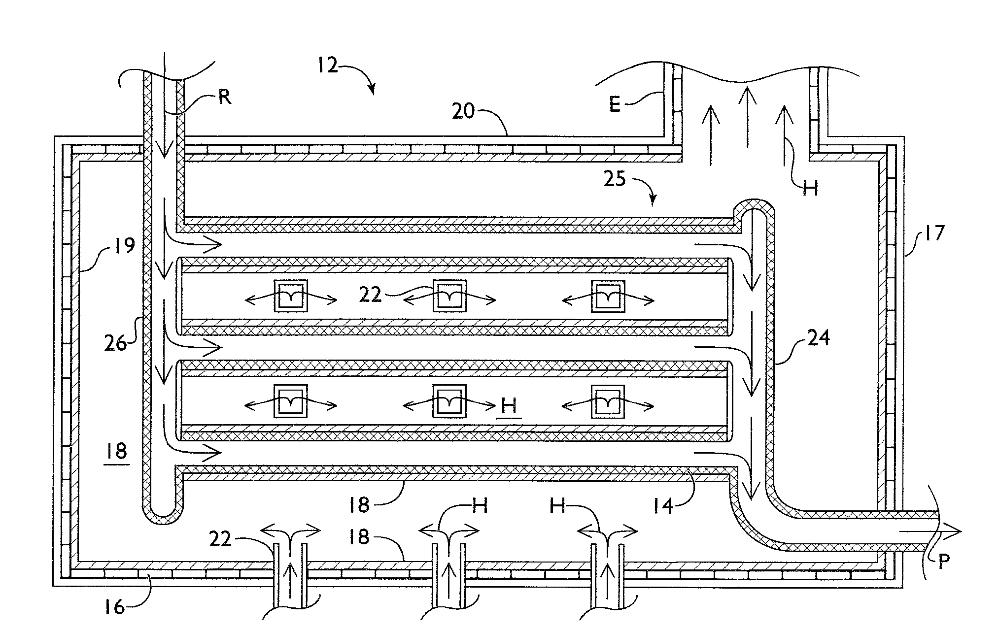
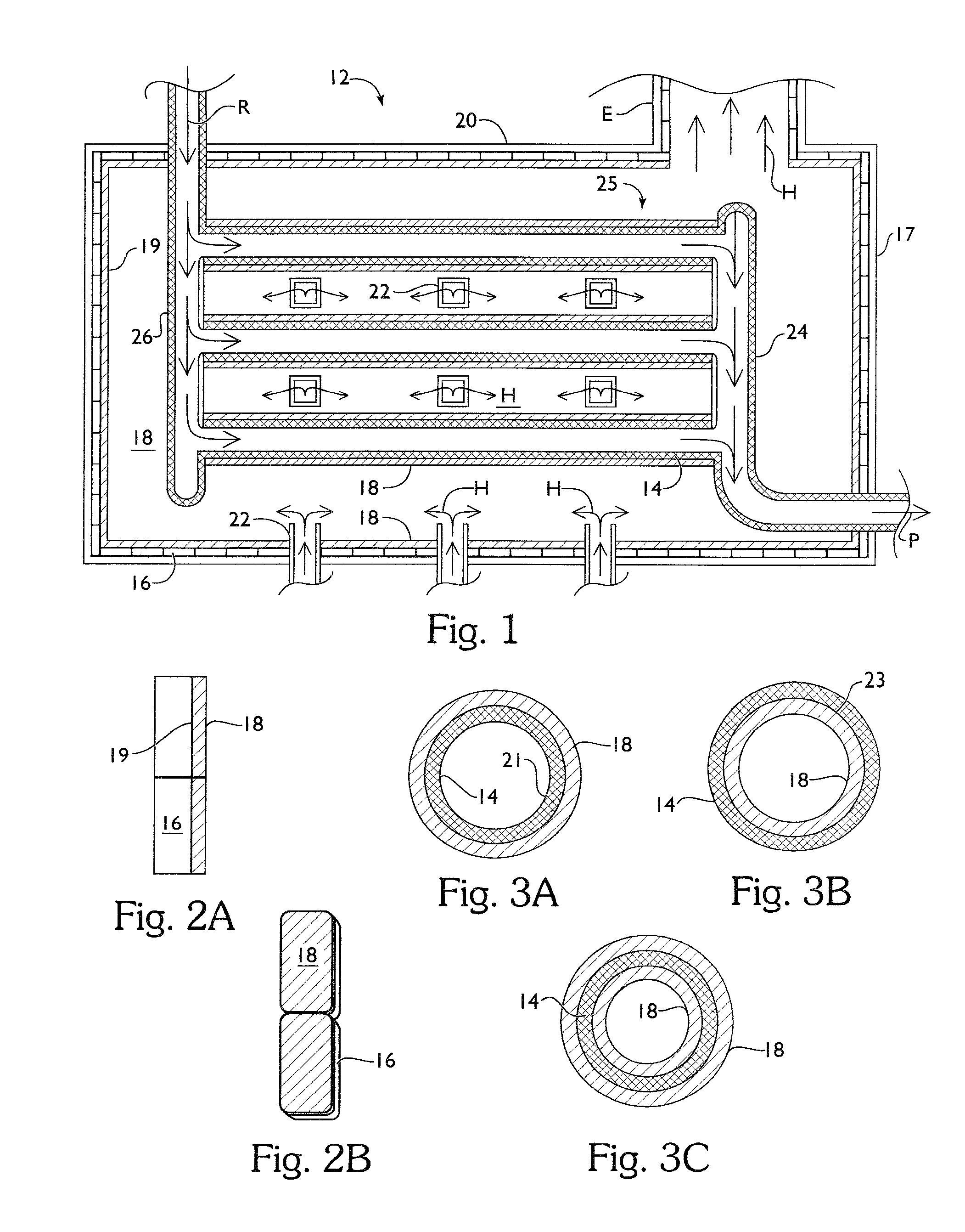
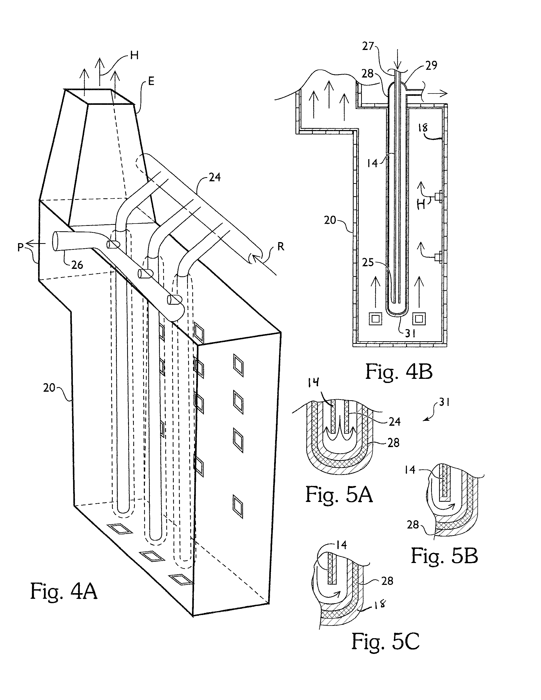
[0040]A cracking furnace construction, as shown in FIG. 1, includes a firebox 12 defining a chamber 20 having walls 17, and containing a plurality of heat H generating burners 22 disposed within the firebox chamber 20, each wall 17 having an internal refractory surface 19 exposed to heat H generated by the burners 22. A tube structure 25 having at least one process tube 14 disposed within the firebox chamber 20, and in fluid communication therethrough, permitting fluid to pass through the firebox chamber 20 while the fluid therein is contained entirely within the tube structure 25. The term “fluid” as used herein includes both liquid and gas. Excess heat H is allowed to vent through an exhaust E. Each process tube 14 has an internal surface 21 defining an interior space, and an external surface 23 directly exposed to the heat H generated within the firebox chamber 20 for thermal communication through the process tube 14 to heat the fluid mixture therein. Each process tube 14, in thi...


PUM

PropertyMeasurementUnit
emissivityaaaaaaaaaa

Abstract

A cracking furnace construction includes a firebox defining a chamber having a high emissivity thermal protective coating disposed on at least part of the refractory walls and / or on process tubes disposed within the chamber. The coating contains an inorganic adhesive for metal / alloy tubes or colloidal silica and / or colloidal alumina for refractory walls or ceramic tubes, a filler, and one or more emissivity agents. A method of coating the firebox chamber includes preparing the surface of the tubes / refractory walls, preparing the coating, and applying the coating to the surface.

Description

BACKGROUND OF THE INVENTION[0001]Pyrolysis furnaces, also known as cracking furnaces, have been used to crack a variety of hydrocarbon feedstocks to ethylene and other valuable olefinic fluids. Cracking at short residence time and high temperature selectively favors the production of ethylene. In order to maximize the conversion and the selectivity of such cracking conversion of the saturated hydrocarbon feedstock into ethylene, for example, it is desirable to input that quantity of heat needed to effect cracking of the saturated hydrocarbon feed very rapidly while minimizing the time that the initial cracking product is exposed to this quantity of cracking heat to fast crack the saturated hydrocarbon feed to ethylene and then quickly remove the formed ethylene from this high heat environment maximizes the final yield of ethylene for the degree of conversion obtained.[0002]Each cracking furnace has a refractory lined firebox containing a multiplicity of high alloy metal or ceramic c...

Claims


Application Information

Patent Timeline
Patent Type & Authority Applications(United States)
IPC IPC(8): B01J8/04F27B14/08B05D1/02
CPCC10G9/20B01J19/02C10G2400/20C04B41/85C04B41/009C04B41/5089C04B35/18C04B41/5035C04B41/507
Inventor OLVER, JOHN W.SIMMONS, JASON ANDREW
Owner EMISSHIELD
Why Eureka
Try Eureka