
Low pressure water-heating solar panel apparatus and method

a solar panel and low-pressure technology, applied in the direction of heat collector mounting/support, light and heating apparatus, other domestic objects, etc., can solve the problems of ineffective efforts with conventional solar panel designs, high labor intensity of mat-type solar panels, and serious disadvantages in construction. achieve the effect of inventive solar panels

Inactive Publication Date: 2009-10-15
THERMOCRAFT INDS
View PDF18 Cites 13 Cited by
  • Summary
  • Abstract
  • Description
  • Claims
  • Application Information

AI Technical Summary

Benefits of technology

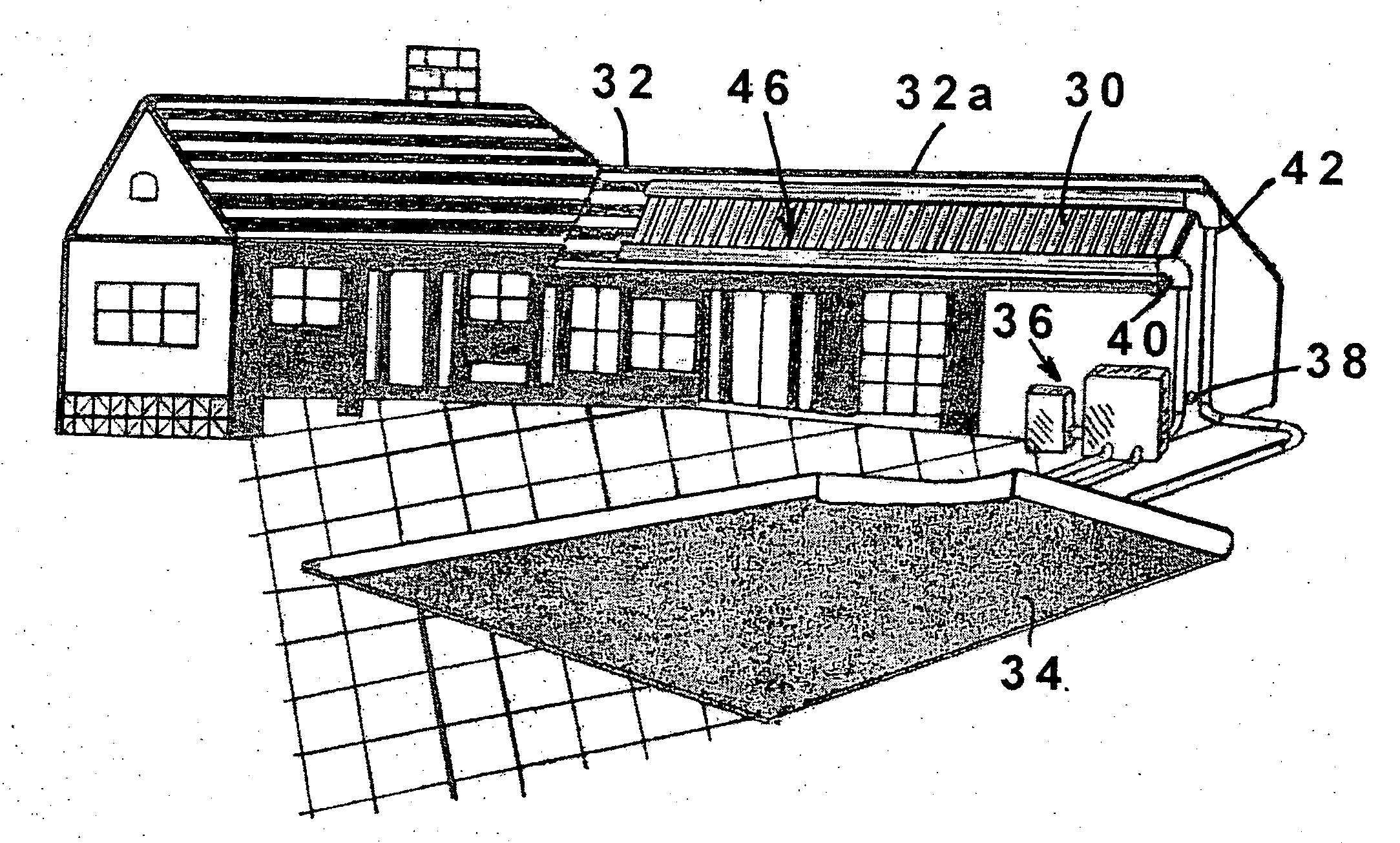
[0015]An advantage of the present invention is the resistance of the inventive solar panel to being broken or being damaged inadvertently during installation or during other work on a mounting rack or roof having the solar panel installed thereon.
[0016]Further, another significant advantage derives from the low-profile nature of the present inventive solar panel, in that the panel “hugs” the roof or rack to which it is mounted, and presents to ambient winds a much less accessible surface under which the wind may catch to lift the solar panel off is rack or roof mounting surface.

Problems solved by technology

This version of mat type solar panel is very labor intensive to install, although it has found some favor with the “do it yourself” home owners.
As will be seen, this construction has a serious disadvantage, especially in parts of the country where freezing temperatures are experienced during winter.
As will be seen, these efforts are ineffective with conventional solar panel designs.
A common problem resulting from the imperfect design of conventional solar panels of the type discussed above is that not all water is able to drain from the panel.
That is, a puddle of water remains in the panel after draining, and may freeze to damage the solar panel.
Such is the case because water may be trapped in one of both of the manifold tubes, and be unable to drain from the panel.
Perhaps these fissures and cracks would not otherwise cause a problem, but over time as these fissures and cracks of the solar panel are widened and weakened by repeated cycles of water freezing and expanding in them, they can lead to leaks of the solar panel.
In fact, such leaks of this type of solar panel in areas experiencing freezing temperatures are a leading cause of warranty claims, customer dissatisfaction, and complaints against this type of solar panel.
As can be seen from the “prior art” Figure, conventional solar panels of this type do not fit closely to the rack or roof surface on which they are mounted, and present an opportunity for high winds to lift the solar panel.
Once such a conventional solar panel is lifted and strong winds get under the solar panel, the chances of the panel being damaged or destroyed are very great.

Method used


Image

  • Low pressure water-heating solar panel apparatus and method
  • Low pressure water-heating solar panel apparatus and method
  • Low pressure water-heating solar panel apparatus and method

Examples


first embodiment

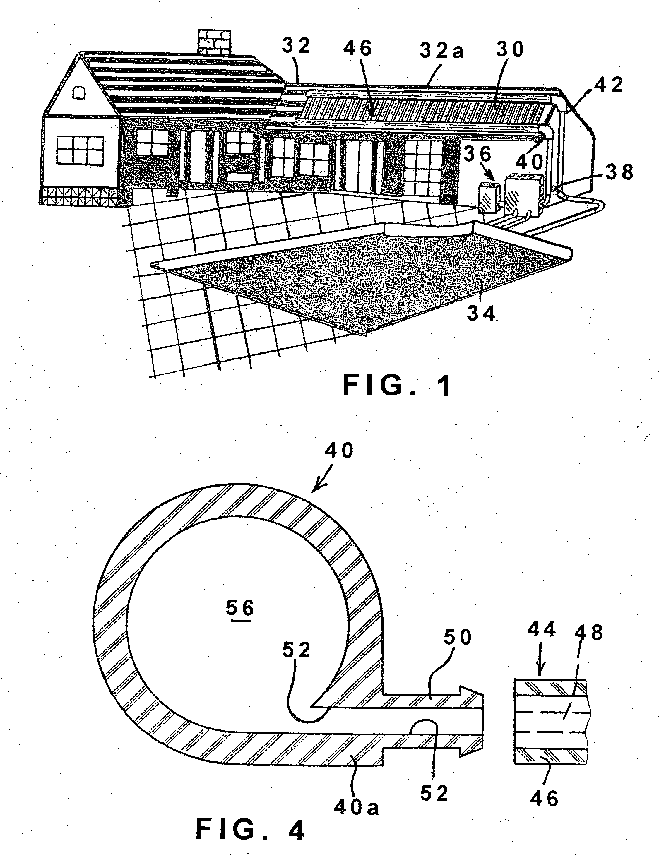
[0039]Turning now to FIG. 5, an alternative embodiment of the present inventive solar panel is illustrated. Because the solar panel of FIG. 5 shares many features with the first embodiment illustrated by reference to FIGS. 1-4, features which are the same, or which are analogous in structure or function to those depicted and described above are indicated on FIG. 5 with the same numeral used above, but increased by one-hundred (100). As is seen in FIG. 5, an inventive solar panel 130 includes a pair of spaced apart manifolds 140, 142 (only one of which is seen in FIG. 5—the other end of the solar panel being a mirror image) which are of tubular construction. The manifold tubes are in flow communication with a mat 144 of plural relatively small tubes 146 interconnected by a relatively thin web 148. Again, these manifold tubes 140, 142 outwardly are preferably not fully round, and each includes an outwardly extending elongate boss 140a, 142a (again, only one of which is seen in FIG. 5)...

second embodiment

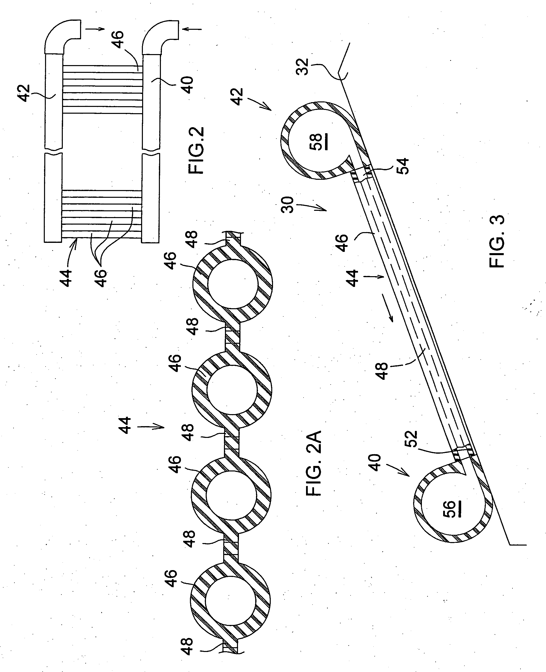
[0040]Again, it is seen that with this second embodiment of the present inventive solar panel, because of the tangential arrangement of the collector tubes 146 to the manifold tubes 140 / 142 the solar panel cannot harbor a trapped puddle of water which is not drained from the solar panel. This is the case because of the tangential entry of the passages 152 / 154 to the manifold passages 156 / 158.

[0041]Turning to FIG. 6, a third alternative embodiment of the present inventive solar panel is illustrated. Because the solar panel of FIG. 6 also shares many features with the first embodiment illustrated by reference to FIGS. 1-4, and with the second embodiment illustrated in FIG. 5, features which are the same, or which are analogous in structure or function, to those indicated in an earlier embodiment are referenced on FIG. 6 with the same numeral used above, but increased by one-hundred (200). Viewing now FIG. 6, an inventive solar panel 230 includes a pair of spaced apart manifolds 240, 2...


PUM

PropertyMeasurementUnit
Pressureaaaaaaaaaa
Angleaaaaaaaaaa
Flow rateaaaaaaaaaa

Abstract

An improved low-pressure, water-heating solar panel provides easier and safer initial installation because it is more resistant to damage by workmen during that installation. Further, after installation, the solar panel is more resistant to damage by high winds because it has a low profile and does not present a gap or space into which high winds can intrude to lift, flap, and damage the solar panel. Also, during freezing weather the improved solar panel is not damaged by freezing of retained water due to its novel internal construction which allows all water to completely drain from the solar panel and prevents any puddling of retained water. Methods of manufacturing the improved solar panel are disclosed.

Description

CROSS REFERENCE TO RELATED APPLICATION[0001]This application is a Continuation-in-Part of U.S. patent application Ser. No. 10 / 979,444, filed 1 Nov. 2004, now U.S. patent Ser. No. ______, issued, and the disclosure of which is incorporated herein by reference to the extent necessary for a complete and enabling disclosure of the present invention.BACKGROUND OF THE INVENTION[0002]The present invention relates generally to a low-pressure, water-heating solar panel of the type generally used to heat water for a swimming pool or spa, although the invention is not so limited. Some of these solar panels are generally referred to as being of “mat” construction or type, because they include a mat of plural relatively small, elongate parallel tubes or conduits, which may be connected to one another in side-by-side parallel array by a web of material, and which are terminated at each of their opposite ends in water flow communication with a respective manifold conduit. The pair of larger manifo...

Claims


Application Information

Patent Timeline
IPC IPC(8): F24J2/46F24J2/04B23P15/26
CPCF16L41/021F16L47/32Y02B10/20Y02E10/44Y10T29/49355F24J2/243F24J2/4647F24J2002/467F24J2/242F24S10/72F24S80/30F24S2025/6007F24S10/73
Inventor WEISE, GARY K.KESL, RICHARD J.
Owner THERMOCRAFT INDS
Learn More