Brake caliper of a disk brake

a technology of brake calipers and disk brakes, which is applied in the direction of brake systems, mechanical equipment, transportation and packaging, etc., can solve the problems of uneven wear of the brake pad, distortion of the backing plate, etc., and achieve the same level of performance, reduce the size, and increase the outer diameter of the piston

Inactive Publication Date: 2009-10-15
NUKABE
View PDF20 Cites 11 Cited by
  • Summary
  • Abstract
  • Description
  • Claims
  • Application Information

AI Technical Summary

Benefits of technology

[0050]In other words, according to the above mode of the second aspect, an ideal seal characteristic can be achieved so as to ideally restore the piston displacement to a proper position, or so as to ideally restore the seal deformation to a proper shape; whereby, a vehicle driver cannot feel any backplay (backlash) when stepping on the brake pedal after a surplus return-back of the brake piston; further, a dragging phenomenon between the brake pad and the brake disk can be avoided during a low brake fluid pressure under a condition that the brake pedal is lightly stepped on as well as during a high brake fluid pressure under such a condition that an ABS (Anti-lock Braking System) works.
[0051]According to the first aspect of the present invention, the pressing part of the piston is of an annular ring shape while the pressing part of a conventional piston is of a solid cylinder shape; thus, the outer diameter of the piston area, namely, the outer diameter of the piston pressing part in the present invention, can be larger than the diameter of the piston pressing part in the conventional piston, even though the respective piston areas are the same; thus, the brake caliper in the present invention can be of a compact structure, and has the same level of performance as in a conventional brake caliper with at least two pairs of pistons.
[0052]In view of a conventional brake caliper having, for instance, two pairs of pistons, a region of the brake pad that is pressed by the pistons extrudes toward the outside of the pressed region, especially t...

Problems solved by technology

This situation causes distortion of the backing plates 1...

Method used


Image

  • Brake caliper of a disk brake
  • Brake caliper of a disk brake
  • Brake caliper of a disk brake

Examples


first embodiment

A First Embodiment

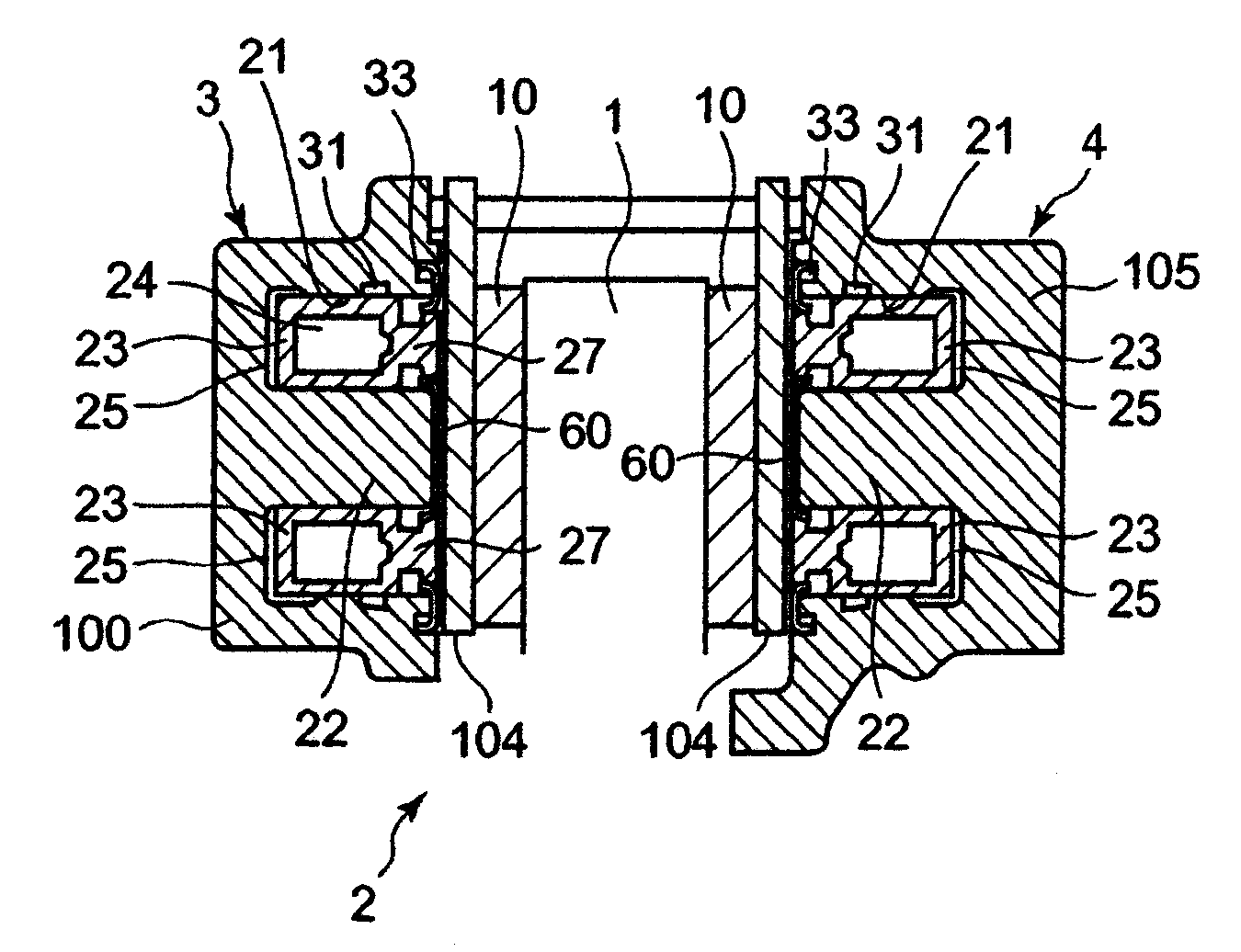
[0110]Hereby, a first embodiment according to the present invention is explained based upon FIGS. 1 and 2 where the same numeral symbols are used as those in FIGS. 13 to 15 as to the conventional technology, in the case where a numeral symbol is common to the present invention and the conventional technology.

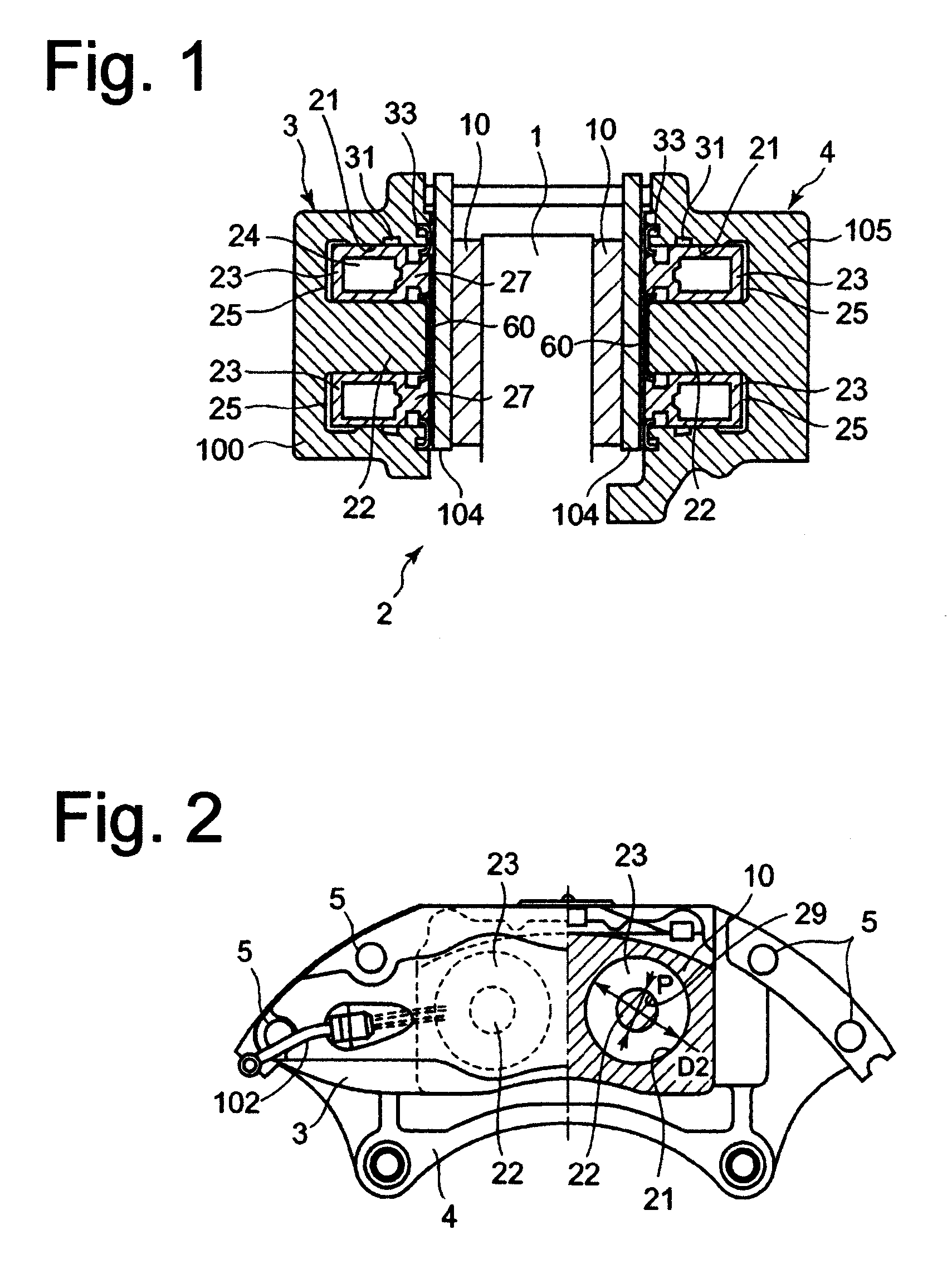
[0111]The whole configuration of a brake caliper 2 in FIGS. 1 and 2 is basically the same as the fitting arrangement of the brake caliper 2 in FIGS. 13 to 15. The brake caliper 2 is configured so as to sandwich a disk rotor 1 with an outer piece 3 and an inner piece 4; and, the brake caliper comprising: the outer piece 3, the inner piece 4, and a bolt 5 fastening the pieces 3 and 4.

[0112]As shown in FIG. 1, the outer piece 3 comprises: an outer caliper body 100; a hole 21 for housing a piston (a brake piston) 23 so that the piston 23 can be guided in the hole 21 as well as sliding along an axis of the hole 21; thereby, a hydraulic chamber 25 is demarcated (impl...

second embodiment

A Second Embodiment

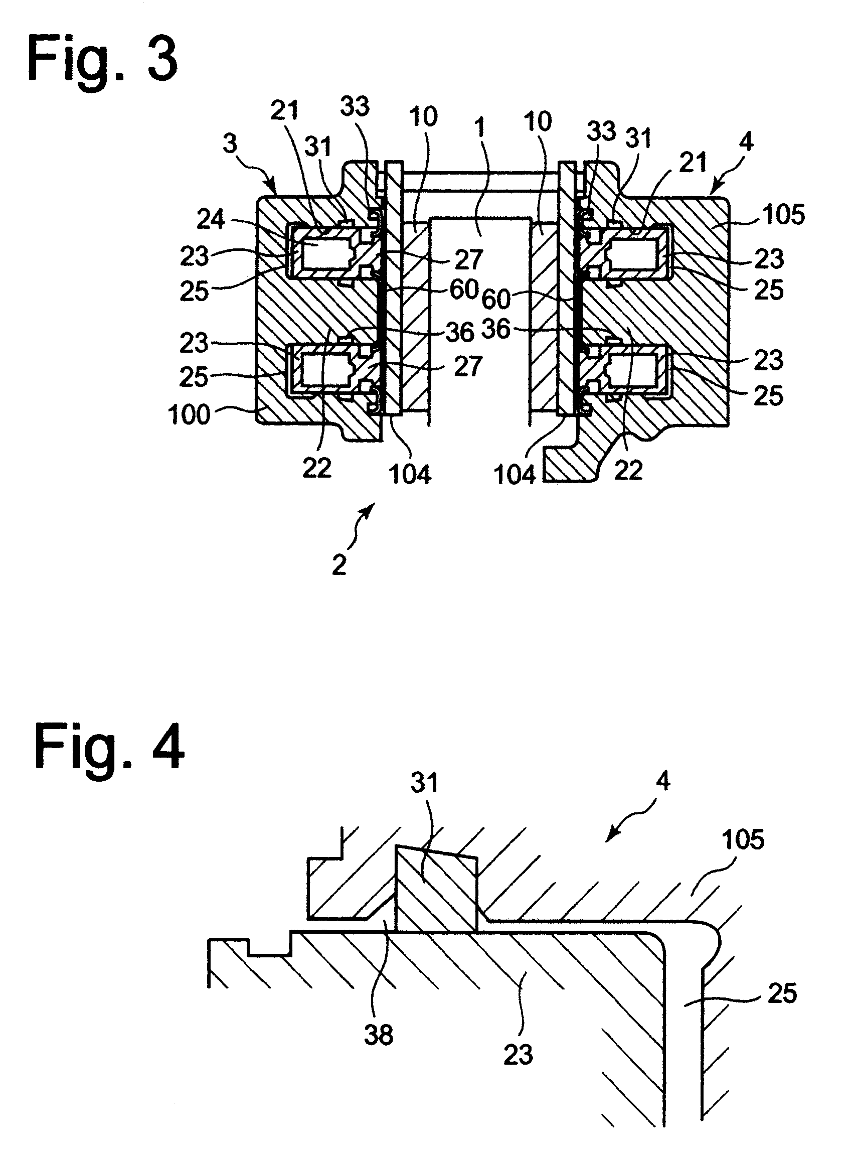
[0129]Hereby, a second embodiment according to the present invention is explained based upon FIGS. 3 to 6.

[0130]In the first embodiment, a square seal 31 is provided as an outer seal (a piston outer seal) between the outer diameter periphery wall of the hole 21 and the outer periphery wall of the piston 23, whereas, in the second embodiment, a square seal 36 is additionally provided as an inner seal (a piston inner seal) between the outer diameter periphery wall of the hole 21.

[0131]It goes without saying that there is no problem, from a functional point of view, in providing the square seal 36 not on the center protrusion 22 side but on the piston 23 side, by providing a groove for the square seal 36 on the piston 23 side.

[0132]As shown in FIG. 3, the piston 23 comes in contact with the square seal 31 on the outer periphery wall of the piston 23, as well as with the square seal 36 on the inner periphery wall of the piston 23. FIG. 4 illustratively shows how the s...

third embodiment

A Third Embodiment

[0140]Hereby, a third embodiment according to the present invention is explained based upon FIG. 7. This embodiment relates to a determination or a designing of the clearance between the piston 23 and the hole 21 for housing the piston 23.

[0141]FIG. 7 depicts the arrangement of the piston 23 and the hole 21 in detail; the piston 23 is placed in the hole 21 with a clearance δ1 between the piston 23 and the caliper body 100 or 105 and a clearance 62 between the piston 23 and the center protrusion 22; in this embodiment, it is basically assumed that the clearance δ1 is not equal to the clearance δ2. In other words, different clearances are applied to the outer side clearance and the inner side clearance as to the annular shaped piston 23 so as to design the brake caliper 2.

[0142]As shown in FIG. 7, the piston 23 strongly presses the disk rotor 1 via the brake pad 10, when a brake fluid pressure is applied in the hydraulic chamber 25 of the caliper body 100 or 105.

[014...


PUM


Abstract

A brake caliper that has the same performance as a brake caliper with multiple pistons despite its compact structure, in which drag resistance between a brake pad and a brake disk is minimized, that is less likely to produce non-uniform wear of brake pad and brake squealing, and whose weight and cost are suppressed. Pistons (23) are formed in a circular hollow cylindrical shape, and apply pressing force to a disk rotor (1) by circular pressing parts. Piston-containing holes (21) recessed in a circular shape and containing the pistons (23) so that they can slide in the axial direction of the pistons are formed in caliper bodies (100, 105).

Description

[0001]This is a continuation of International Application PCT / JP2007 / 070279 (published as WO 2008 / 047840 A1) having an international filing date of Oct. 17, 2007, which is based on and claims priority from JP 2006-284594 filed on Oct. 19, 2006, JP 2007-013658 filed on Jan. 24, 2007 and JP 2007-137353 filed on May 24, 2007, the contents of which is incorporated herein in its entirety by reference.FIELD OF THE INVENTION[0002]The present invention relates to a brake caliper of a disk brake that is used in a vehicle such as an automobile or a motorcycle.DESCRIPTION OF THE RELATED ARTS[0003]There are two types of brake caliper; a brake caliper of the first type has at least one piston on only one side of a brake disk (a disk to be braked), while a brake caliper of the second type has at least one piston on each side of a brake disk; in the case of the second type, a piston on one side and a piston on the other side face each other across the brake disk. Many performance cars adopt a disk...

Claims


Application Information

Patent Timeline
IPC IPC(8): F16D65/20B60T11/00F16D65/18
CPCF16D55/228F16D65/18F16D2125/06F16D2055/0091F16D2121/02F16D2055/002F16D65/095F16D55/224
Inventor KURITA, SHOZO
Owner NUKABE
Why Eureka
Try Eureka