Stabilizing and directional-control surface of aircraft

a technology of directional control and aircraft, which is applied in the direction of metal working apparatus, transportation and packaging, weapons, etc., can solve the problems of increasing the complexity of the aircraft and its flight control system structure, increasing fuel consumption and noise, and increasing the weight and drag of the aircraft, so as to improve the energy efficiency and reduce the time for centring the aircraft. , the effect of increasing the weight of the uni

Inactive Publication Date: 2009-10-15
AIRBUS OPERATIONS SL
View PDF18 Cites 19 Cited by
  • Summary
  • Abstract
  • Description
  • Claims
  • Application Information

AI Technical Summary

Benefits of technology

[0010]Another advantage of the present invention relative to other existing solutions is its simplicity. There are many inventions (U.S. Pat. No. 2,643,833, U.S. Pat. No. 5,681,010, U.S. Pat. No. 2,941,752) that claim the concept of adjusting the area of the tail unit in relation to the flight phase of the aircraft, but they add a great quantity of mechanical elements to the structure, which leads to increased weight of the unit and therefore poorer energy efficiency, as well as various drawbacks, such as a penalty in the time for centring the aircraft.
[0011]The present invention aims to solve the drawbacks mentioned above.
[0012]The present invention relates to a technical solution that improves, especially at takeoff (very low aircraft speeds) but also in the other phases of flight, the behaviour of an aircraft when it is acted upon by an unexpected yawing moment through causes intrinsic to the aeroplane such as failure of one of its engines, although this yawing moment may also be due to unbalanced transport of external loads or may arise from factors external to the aircraft, for example cross-wind or flooding of part of the takeoff runway.
[0013]Thus, the aim of the invention is to reduce the area of the stabilizing and directional-control surface of aircraft, comprising a vertical stabilizer and a rudder, specifically reduction of the surface area of the vertical stabilizer, without affecting the requirements of said stabilizing and directional-control surface as a control surface. The invention achieves this aim by means of a stabilizing and directional-control surface in which basically the surface area of the rudder is adjusted at takeoff of the aircraft and in conditions in which the aeroplane is subjected to a strong yawing moment as a consequence of failure of one of its power plants, or resulting from the transport of external loads, from flooding of part of the takeoff runway or from the effects of a cross-wind, among others.
[0014]One of the advantages of the invention is its simplicity of application for aircraft for civil use that are currently available, as well as the fact that it has little effect on the other aerodynamic surfaces of the aircraft, both in its use and in automation of its control.
[0018]an actuating system of the structure proper of the rudder, which permits said rudder to open and thus permits subsequent extension of the internal profile thereof, as well as the subsequent closure of the structure of the rudder once the internal profile has been retracted.

Problems solved by technology

The problems that arise in the known solutions of this type relate to the increase in complexity of the structure of the aircraft and of its flight control systems.
This gives rise to an increase in weight and increased drag of the aircraft, which leads to an increase in fuel consumption and noise.
To have lower minimum control speeds implies that the surface area of the vertical stabilizer and the surface area and power of the rudder should be greater, which means a penalty in weight and drag, as well as increasing the costs of manufacture, the resultant weight of the structure and the fuel cost in flight.
Solutions of this type increase the complexity of the control systems of the aeroplane and limit the crew's capacity for reaction and piloting to the maximum deflection of the rudder, an inadequate manoeuvre unless it is coupled with activation of the systems described.
Conversely, the use of spoilers or ailerons (aerodynamic surfaces of the wings) can create a rolling moment on the aircraft, which will be controlled by the use of other surfaces, which will give rise either to an unnecessary increase in work load for the pilot, or to greater complexity of the automatic systems for flight control.
That is, increase of the aerodynamic control surfaces on the wing leads to increased drag and therefore reduces the thrust capability of the engines, i.e. the aeroplane's ability to accelerate at a critical moment when this characteristic can prove decisive.
Another drawback of having more aerodynamic surfaces on the aircraft is that their actuation results in a considerable increase in noise.
There are many inventions (U.S. Pat. No. 2,643,833, U.S. Pat. No. 5,681,010, U.S. Pat. No. 2,941,752) that claim the concept of adjusting the area of the tail unit in relation to the flight phase of the aircraft, but they add a great quantity of mechanical elements to the structure, which leads to increased weight of the unit and therefore poorer energy efficiency, as well as various drawbacks, such as a penalty in the time for centring the aircraft.

Method used


Image

  • Stabilizing and directional-control surface of aircraft
  • Stabilizing and directional-control surface of aircraft
  • Stabilizing and directional-control surface of aircraft

Examples


first embodiment

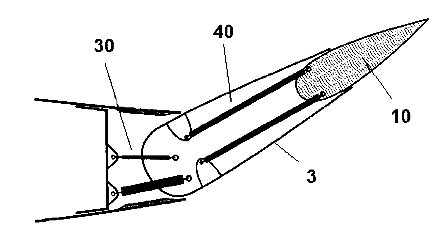
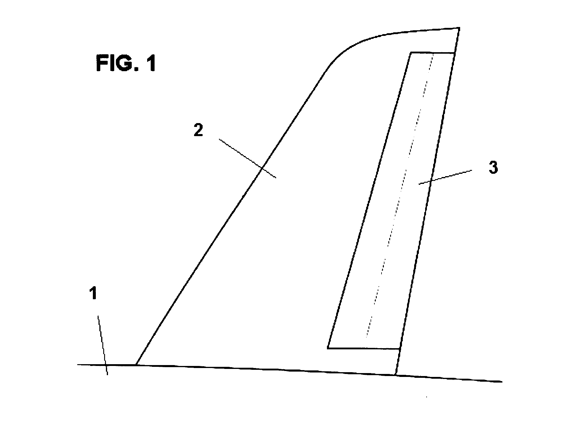
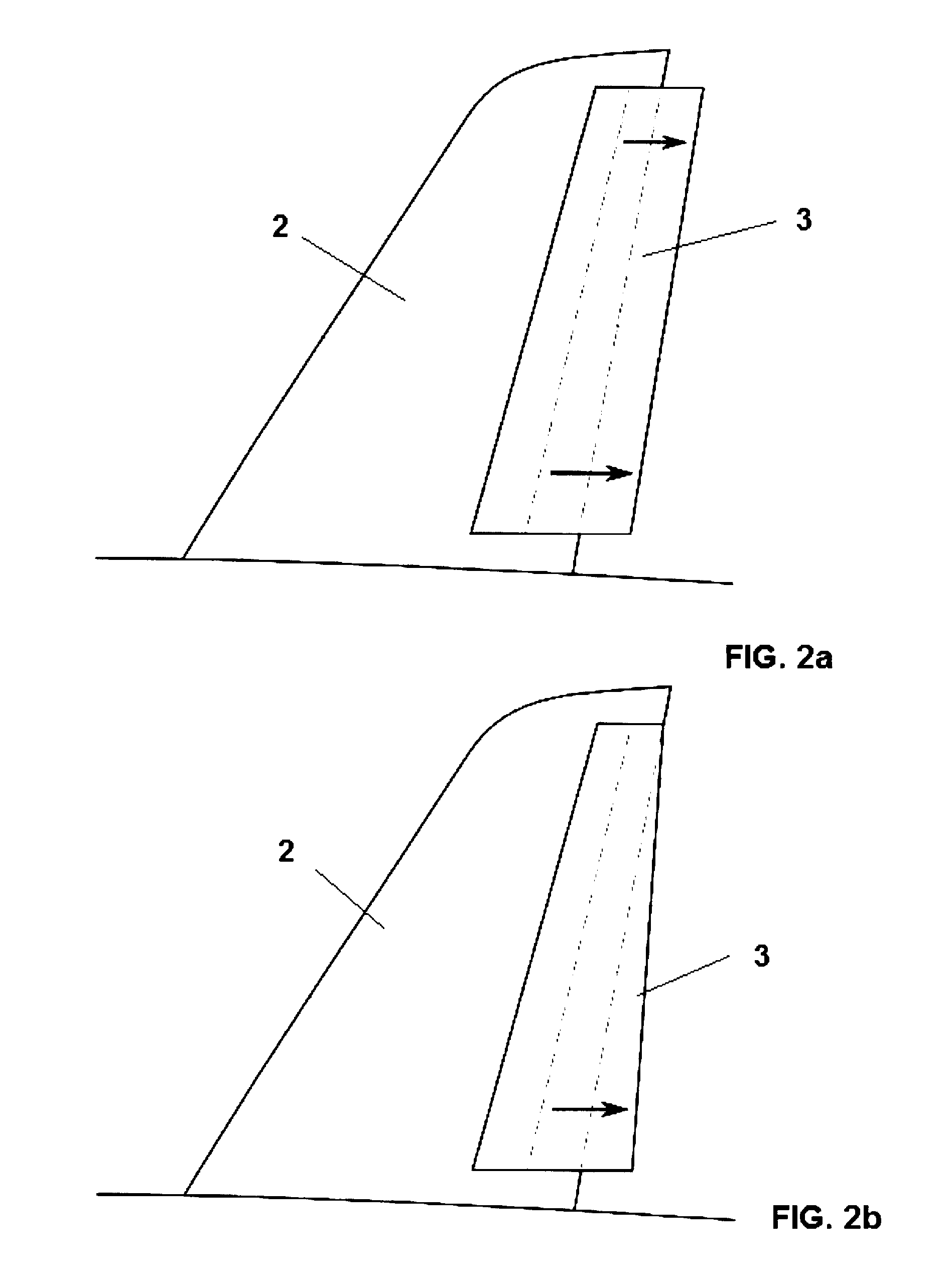
[0033]FIGS. 3a and 3b show two positions, in a schematic top view, of the rudder 3 of an aircraft, in retracted mode, according to the present invention. The two positions of the rudder 3 in FIGS. 3a and 3b are: without being deflected (or deflection 0°) in FIG. 3a, and deflected in FIG. 3b. These figures also show part of the plan view of the vertical stabilizer 2 and of its torsion box-beam 4. The rudder 3 is anchored on the surface of the vertical stabilizer 2 in a conventional manner. Thus, we have a deflecting system 30 that comprises at least two actuators 7, with each actuator 7 anchored to the torsion box-beam 4 of the vertical stabilizer 2 by means of a fitting of type 8, and to the rudder 3 by means of a catch 9. The deflecting system 30 provides the appropriate deflection of the rudder 3. Rudder 3 comprises in its turn an internal profile 10, a fundamental structure for increasing the aerodynamic surface area on extension of the rudder 3.

[0034]FIGS. 4a and 4b show two pos...

second embodiment

[0038]As can be seen in FIGS. 5a and 5b, corresponding to the present invention, it comprises an actuating system 40 for the extension and retraction of the internal profile 10 of the rudder 3 that comprises at least one actuator 57, said actuator 57 being anchored to the structure of the rudder 3 by means of a fitting of type 58, and to the internal profile 10 of the rudder 3 by means of a catch 59. By means of the aforementioned actuating system 40, it is possible to extend and retract the internal profile 10 and therefore increase or reduce the aerodynamic surface of the rudder 3 in relation to the circumstances explained previously.

[0039]This second embodiment of the invention (FIGS. 5a and 5b) further incorporates a guidance system 17 which guides the movement of the internal profile 10 of the rudder 3. The guidance system 17 comprises a system of bearings 18 and a bar 19. The bar 19 is connected to the internal profile 10, so that when the actuating system 40 induces a transla...

third embodiment

[0043]Thus, the operation of FIGS. 6a and 6b corresponding to the invention will consist of extension and retraction of the rudder 3 by means of the elastic system 20 and the cable-controlled movement system 21, aided by the guidance system 17. In this way, when it is necessary to extend the rudder 3 of the vertical stabilizer 2 based on the flight requirements, the movement of the cable 22 will be released in the motor 23, so that the elastic system 20 will be activated and will produce a fast movement of the internal profile 10, but moreover a movement that is controlled by the guidance system 17, with the result that the rudder 3 assumes its extended configuration. When the flying conditions permit the area of the vertical stabilizer 2 to be reduced, the internal profile 10 will be retracted by take-up of the cable 22, through actuation of motor 23. Both the movement of extension and that of retraction of the internal profile 10 of the rudder 3 will be controlled by the guidance ...


PUM


Abstract

Stabilizing and directional-control surface of an aircraft, said surface comprising a vertical stabilizer (2) and a rudder (3), it being possible for said rudder (3) to be deflected relative to the vertical stabilizer (2), and moreover the rudder (3) comprises an internal profile (10) that can be extended and retracted by means of an actuating system (40) relative to the rest of the structure of the rudder (3), so that the stabilizing and control surface, in the retracted position of the internal profile (10) of the rudder (3), is an excellent aerodynamic surface in normal flying conditions, and at the same time increase of the aerodynamic control surface of the vertical stabilizer (2) is achieved for requirements of controllability of the aircraft at low speeds of said aircraft and against strong yawing moments acting thereon, in the position in which the internal profile (10) of the rudder (3) is extended, and moreover the structure of the rudder (3) can be opened, to permit extension of the internal profile (10), and said structure closes once the internal profile (10) is fully extended, so that the rudder (3) forms, with the extended internal profile (10), a structure that preserves its properties of aerodynamic surface and continuity of flow.

Description

FIELD OF THE INVENTION[0001]The present invention relates to a stabilizing and directional-control surface of aircraft, capable of stabilizing and controlling the direction of the aircraft when the latter is subjected in particular to unexpected strong yawing moments.BACKGROUND OF THE INVENTION[0002]Aircraft surfaces that provide stability and directional control of the aircraft are well known and have been extensively investigated. Fundamental among these are the vertical stabilizer and the rudder. The vertical stabilizer ensures that the nose of the aeroplane is oriented in the direction of flight, and the rudder opposes the yawing moments acting upon the aircraft, when the lateral direction of flight of said aircraft is being controlled.[0003]The size and the operational power of the rudder are determined by, in addition to the aerodynamic requirements for the aircraft, several other factors intrinsic to the aircraft, for example if a fault develops in one of its power plants, an...

Claims


Application Information

Patent Timeline
Patent Type & Authority Applications(United States)
IPC IPC(8): B64C9/00B64C9/02B64C9/34F42B99/00B64D47/00B26D5/08
CPCB64C5/18B64C9/00Y02T50/44Y02T50/32B64C9/08Y02T50/30Y02T50/40
Inventor VERDE PRECKLER, JORGE PABLOVIZARRO TORIBIO, JOSE MIGUEL
Owner AIRBUS OPERATIONS SL
Why Eureka
Try Eureka