Method of power amplifier predistortion adaptation using compression detection

a technology of compression detection and power amplifier, applied in the field of predistortion adaptation of power amplifier, can solve the problems of affecting the modulation accuracy of waveform, generating potentially excessive noise in adjacent carrier regions, and real amplifiers only linear within certain practical limits

Inactive Publication Date: 2009-10-15
SAMSUNG ELECTRONICS CO LTD
View PDF4 Cites 87 Cited by
  • Summary
  • Abstract
  • Description
  • Claims
  • Application Information

AI Technical Summary

Benefits of technology

[0011]It is still another object of the present invention to reduce the power consumption of the power amplifier circuit.

Problems solved by technology

Yet at an operating output power at which the amplifier operates efficiently, the amplifier often undesirably generates a level of distortion on the waveform that corrupts the modulation accuracy of the waveform and generates potentially excessive noise in adjacent carrier regions.
An ideal amplifier would be a totally linear device, but real amplifiers are only linear within certain practical limits.
When an input signal is increased, the output also increases until a saturation point is reached where some part of the amplifier becomes saturated and cannot produce any more output; this is called clipping, and results in distortion.
Without any form of linearization, a signal can only be transmitted within the linear operating region of the power amplifier with very poor efficiency.
Between the high PAPR of the OFDM waveform and the low EVM requirements of the uplink, the net result is that the terminal power amplifier operates at a relatively poor efficiency.
This causes a much greater drain on the terminal battery thereby causing a relatively short battery life.
Historically, digital predistortion has not been widely implemented in terminal transmitters because the power dissipation of the added signal processing circuitry has more than offset the reduction on power amplifier current drain.
Therefore digital predistortion within wireless systems has often been limited to the base station transmitter operating at 10 to 40 watts.

Method used


Image

  • Method of power amplifier predistortion adaptation using compression detection
  • Method of power amplifier predistortion adaptation using compression detection
  • Method of power amplifier predistortion adaptation using compression detection

Examples


Embodiment Construction

[0032]In the following disclosure, AM / AM stands for amplitude-to-amplitude, and AM / PM stands for amplitude-to-phase.

[0033]The invention will now be described more fully hereinafter with reference to the accompanying drawings.

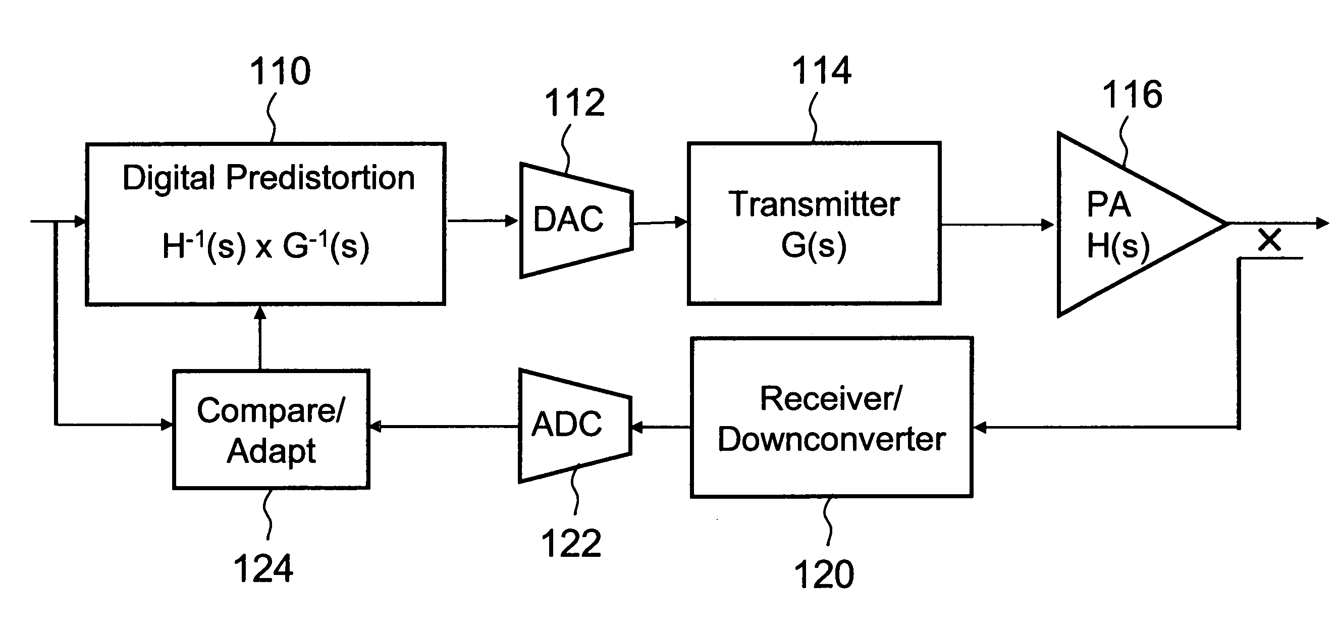
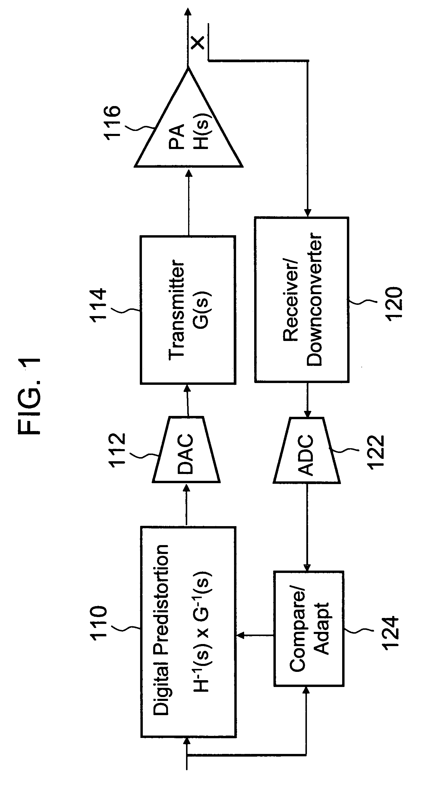
[0034]FIG. 1 illustrates an adaptive digital predistortion architecture with feedback. In most contemporary forms of digital predistortion, a digitized baseband waveform is predistorted by a Predistortion block 110 using a certain transfer function that represents the inverse of the expected power amplifier distortion characteristics. The predistorted waveform is converted by a digital-to-analog converter (DAC) 112. In order to ensure this predistortion transfer function is accurate and to compensate for variations of the characteristics of transmitter 114 and power amplifier 116, the sample of the output waveform of power amplifier 116 along with its intermodulation products are downconverted, demodulated, digitized and this digitized feedback waveform is compa...


PUM


Abstract

A method of power amplifier predistortion that makes use of a compression detector circuit in a feedback loop in order to adapt the channel gain for changing transmitter behavior. By monitoring the compression behavior of the amplifier, the signal is scaled to compensate for gain and compression point variations in the power amplifier and transmitter, while keeping a predistortion correction function constant.

Description

BACKGROUND OF THE INVENTION[0001]1. Field of the Invention[0002]The present invention relates to a method for adapting power amplifier predistortion by using compression detection feedback.[0003]2. Description of the Related Art[0004]In wireless systems a power amplifier is frequently used as one of the final transmitter stages for the purpose of amplifying the transmitted waveform to the appropriate level to provide adequate signal-to-noise ratio over the link. To achieve reasonable efficiency from a power amplifier, the amplifier is often operated near its compression point. Yet at an operating output power at which the amplifier operates efficiently, the amplifier often undesirably generates a level of distortion on the waveform that corrupts the modulation accuracy of the waveform and generates potentially excessive noise in adjacent carrier regions.[0005]Contemporarily, many forms of linearization have been developed in an effort to recover the modulation accuracy of the power ...

Claims


Application Information

Patent Timeline
Patent Type & Authority Applications(United States)
IPC IPC(8): H03F1/26G01R19/00
CPCH03F1/3247H03F1/3288H04L27/368H03F2201/3233H03F3/24
Inventor BROBSTON, MICHAEL LEE
Owner SAMSUNG ELECTRONICS CO LTD
Why Eureka
Try Eureka