
Method and apparatus for reducing frequency memory effects in RF power amplifiers

Active Publication Date: 2009-10-15
TELEFON AB LM ERICSSON (PUBL)
View PDF4 Cites 16 Cited by
  • Summary
  • Abstract
  • Description
  • Claims
  • Application Information

AI Technical Summary

Benefits of technology

[0021]According to a third aspect of the invention, the above stated problem is solved by means of a base station, which base station includes a predistorter that reduces frequency memory effects in a RF power amplifier of said base station.
[0027]Another advantage is that the predistorter according to the invention can easily be combined with other predistorters as will be described and illustrated.

Problems solved by technology

None of the above mentioned prior art predistorters take variations in the drain voltage into account in a manageable way and are therefore not able to compensate for memory effects caused by such variations in a satisfactory way.

Method used


Image

  • Method and apparatus for reducing frequency memory effects in RF power amplifiers
  • Method and apparatus for reducing frequency memory effects in RF power amplifiers
  • Method and apparatus for reducing frequency memory effects in RF power amplifiers

Examples


first embodiment

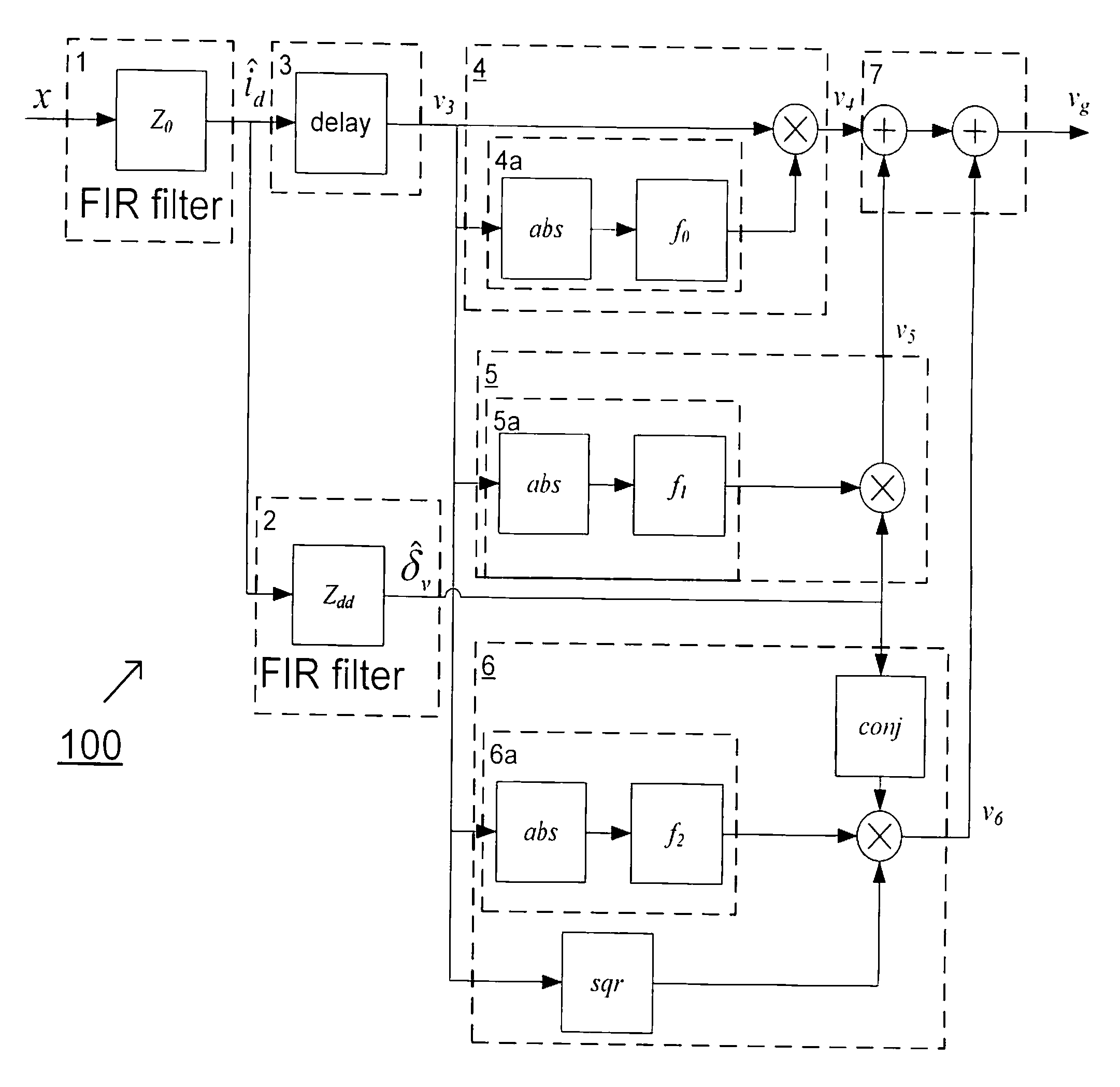
[0067]Using equations (8) and (9), a series expansion of the gate voltage function vg[n] similar to the series expansion introduced earlier in equation (4) gives us the following expression that defines a predistorter in accordance with the present invention:

vg[n]=îd[n−k]·f0(|îd[n−k]|)+{circumflex over (δ)}v[n]·f1(|îd[n−k]|)+{circumflex over (δ)}*v[n]·îd2[n−k]·f2(|îd[n−k]|)   (10)

[0068]The function f0(|îd[n−k]|) in equation (10) represents the memoryless behaviour of the amplifier, i.e. it's output is the memoryless large-signal gain of the predistorter, and îd[n−k] represents a selected time-delayed version of the estimate of the drain current îd. The functions f1(|îd[n−k]|) and f2(|îd[n−k]|) describes the amplifiers sensitivity to fluctuations in the drain voltage for different output amplitudes.

[0069]Note that when designing a predistorter according to equation (10), the functions f0(|îd[n]|), f1(|îd[n]|), f2(îd[n]|) and the filter Zdd should preferably be chosen or adapted in su...

second embodiment

[0071]The gate voltage function vg[n] given by equation (11) defines the output of the predistorter according to the present invention. This gate voltage is also the desired input to the power amplifier PA according to equation (6) or equation (7).

[0072]Note that the generalized expression of the gate voltage vg[n] as given by equation (11) has the advantage of being linear in f0(|îd[n−k]|), h1m(|îd[n−k]|), and h2m(|îd[n−k]|), making the predistorter according to the invention much easier to adapt. Also, because f0(îd[n−k]|), h1m(|îd[n−k]|), and h2m(|îd[n−k]|) are implemented using nonlinear filters, the predistorter according to the invention is fairly simple to implement and does not require complex calculations to be performed.

[0073]As mentioned earlier it is not necessary to stop the series expansion after the first order, higher order terms can be included as well. Equation (12) below represents an expression of the gain voltage or similarly the predistorter that includes secon...


PUM


Abstract

The present invention relates to a predistorter for reducing memory effects in RF power amplifiers. The invention also relates to a method for reducing memory effects in RF power amplifiers and to a base station including such a predistorter. A predistorter according to the invention includes first means (1) for generating a first signal component, which is an estimate of a drain current of said amplifier, which means (1) for generating said first signal component comprises a linear filter, second means (8) for generating a second signal component as a function of said first signal component and at least one first gain function; third means (9) for generating a third signal component as a function of a conjugate of said first signal component and at least one second gain function, and fourth means (7) for combining at least said second signal component and said third signal component to form an output signal. The output signal from the predistorter is further used as input to the power amplifier, which when amplified reduces the memory effects of the amplifier.

Description

TECHNICAL FIELD OF THE INVENTION[0001]The present invention relates to power amplifying techniques in general and to a method and apparatuses for reducing frequency memory effects in (RF) power amplifiers in particular.DESCRIPTION OF RELATED ART[0002]Power amplifiers are indispensable components in a communication system and are known to add more or less distortion to the signal they are designed to amplify, especially in multicarrier telecommunications systems (e.g. WCDMA) which are particularly sensitive to distortion. The reason for this is that power amplifiers have a non-linear input-output signal characteristic. This results in a broadened spectrum around the desired amplified signal, and an unwanted in-band component of the signal, which lead to bad system performance.[0003]To overcome this problem of distortion or to decrease the effects of non-linearity, several linearization schemes could be used. One such linearization scheme is known as feed-forward, where a signal is in...

Claims


Application Information

Patent Timeline
IPC IPC(8): H03F1/32H03F3/16
CPCH03F1/3241H03F2201/3224H03F2201/3209H03F3/187H03F1/0288
Inventor KLINGBERG, MATSFONDEN, TONY
Owner TELEFON AB LM ERICSSON (PUBL)
Learn More