Bridge synchronous rectifier

a bridge rectifier and synchronous technology, applied in the field of full-wave rectifiers, can solve the problems of ineffective diodes, forward voltage drop, and inefficiency of diodes

Active Publication Date: 2009-10-15
POWERMAT TECHNOLOGIES
View PDF100 Cites 94 Cited by
  • Summary
  • Abstract
  • Description
  • Claims
  • Application Information

AI Technical Summary

Problems solved by technology

A typical bridge rectifier is the Graetz circuit or diode bridge which consists of four diodes arranged in a bridge circuit as shown in FIG. 1a. It will be noted, however, that diodes are inherently inefficient conductors and this produces a number of well known problems.
One problem resulting from the inefficiency of diodes is that they produce a forward voltage drop.
A further problem results from the heat dissipated by diodes, particularly in high frequency switching power supplies.
Apart from reducing overall efficiency of the power converter, resulting high temperatures also reduce the reliability of components.
Much design effort is typically required to overcome this problem, and other factors such as the dimensions of the system may be compromised as a result.
However, if the remaining two diodes are replaced by MOSFETs and also draw gate signals directly from the input voltage, it is difficult to avoid short circuiting between the input and / or the output terminals of the bridge rectifier.

Method used


Image

  • Bridge synchronous rectifier
  • Bridge synchronous rectifier
  • Bridge synchronous rectifier

Examples


Embodiment Construction

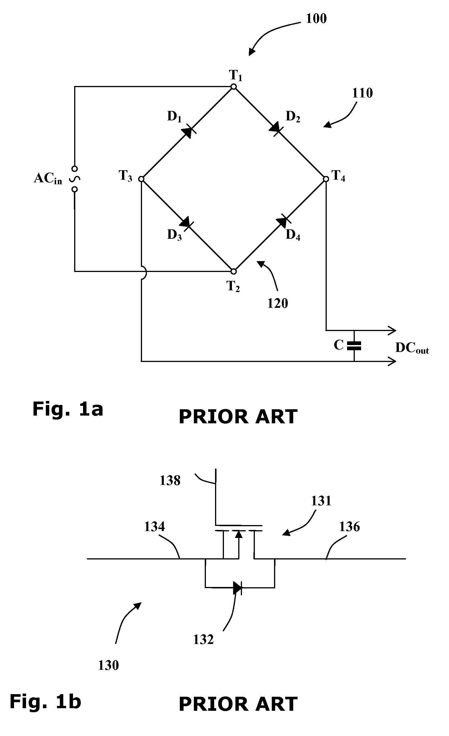
[0051]Reference is now made to FIG. 1a showing a circuit diagram of a typical full-wave rectifier 100 of the prior art. The rectifier has two input terminals T1 and T2 and two output terminals T3 and T4. When an alternating current source ACin is wired to the two input terminals T1 and T2, a direct current output DCout may be drawn from the two output terminals T3 and T4 of the rectifier 100.

[0052]Four diodes D1-4 are arranged so that two diodes D1 and D2 form a first branch 110 of a Graetz circuit and the other two diodes D3 and D4 form a second branch 120 of the Graetz circuit. The anodes of two upstream diodes D1 and D3 are wired to the first output terminal T3 and the cathodes of the two downstream diodes D2 and D4 are wired to the second output terminal T4. The cathode of the first upstream diode D1 and the anode of first downstream diode D2 are wired to the first input terminal T1 and the cathode of the second upstream diode D3 and the anode of second downstream diode D4 are w...


PUM


Abstract

A current-triggered synchro-rectifier comprising an electronic switch configured to be in its ON setting when the current flowing through its cathode exceeds a predetermined threshold. The electronic switch may include a half-wave rectifier wired to the source terminal and the drain terminal of a MOSFET device, and a current monitor configured to monitor the drain-current flowing through the drain terminal. The current monitor sends a gate signal to the gate terminal such that the MOSFET is switched to its ON state when the drain-current exceeds a first threshold current and the MOSFET is switched to its OFF state when the drain-current falls below a second threshold current. Usefully, the synchro-rectifier may be incorporated into a full-wave rectifier.

Description

CROSS-REFERENCE TO RELATED APPLICATION[0001]This application is based upon and claims the benefit of the filing date of co-pending, commonly assigned U.S. Provisional Patent Application Ser. No. 61 / 071,151, filed on Apr. 15, 2008, which is incorporated herein by reference in its entirety.FIELD OF THE INVENTION[0002]The present invention is directed to providing a full-wave rectifier having low power loss characteristics.BACKGROUND OF THE INVENTION[0003]Power converters are used to interface between power sources and electrical devices. Because alternating current is preferred for efficient power transmission, power sources typically provide power at alternating current. On the other hand the operation of many electrical devices requires direct current. In order to provide direct current for such devices from alternating current, the power sources, power converters need to convert the current supplied from alternating to direct, and use rectifiers for this purpose.[0004]Bridge rectif...

Claims


Application Information

Patent Timeline
Patent Type & Authority Applications(United States)
IPC IPC(8): H02M7/12
CPCH02M7/217
Inventor LEIBOVITZ, ALFRED
Owner POWERMAT TECHNOLOGIES
Why Eureka
Try Eureka