
Fuel cell system

a fuel cell and system technology, applied in the direction of fuel cells, solid electrolyte fuel cells, electrical equipment, etc., can solve problems such as affecting system reliability, and achieve the effect of accurate determination

Inactive Publication Date: 2009-10-15
NISSAN MOTOR CO LTD
View PDF4 Cites 26 Cited by
  • Summary
  • Abstract
  • Description
  • Claims
  • Application Information

AI Technical Summary

Benefits of technology

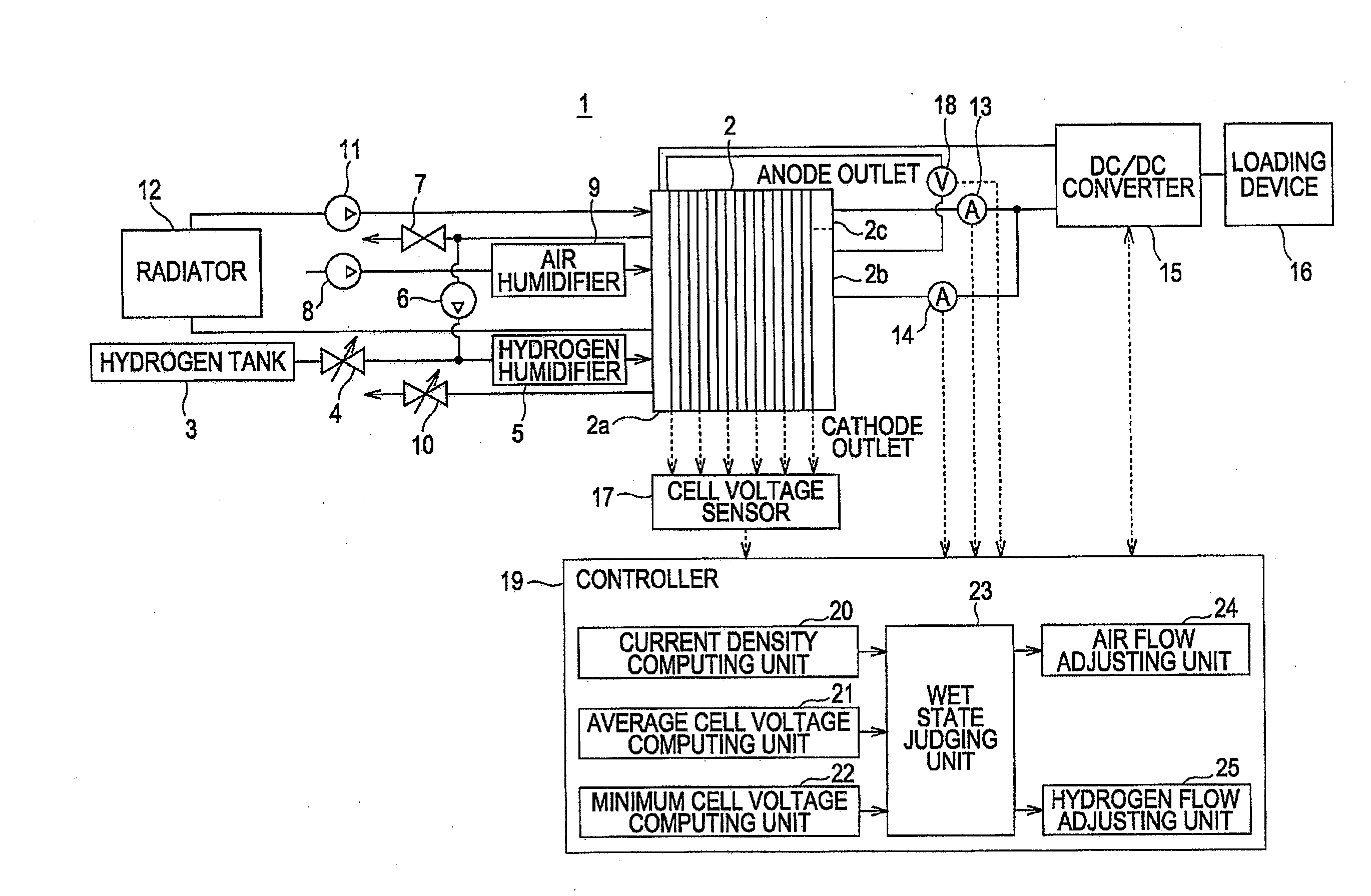
The present invention provides a fuel cell system and method for accurately determining the wet state of the fuel cell without degrading the reliability of the system. This is achieved by detecting the voltage and current in the fuel cell stack, and using a wet state-judging unit to determine the difference between the average cell voltage and the minimum cell voltage, as well as the difference between the stack current density and the anode outlet local current density. This allows for accurate detection of the wet state of the fuel cell without the need for costly and unreliable methods such as voltage mapping or visual inspection.

Problems solved by technology

However, such an operation is problematic in actual vehicle fuel cell systems because increasing the cathode gas flow without identifying whether the cell is dry or clogged with water will seriously impair reliability of the system.
This is because it is possible that if the cathode gas flow is increased while the fuel cell is rather dry and the fuel cell voltage is low, then drying will rapidly proceed, thereby possibly leading to dry-outs.

Method used


Image

  • Fuel cell system
  • Fuel cell system
  • Fuel cell system

Examples


Embodiment Construction

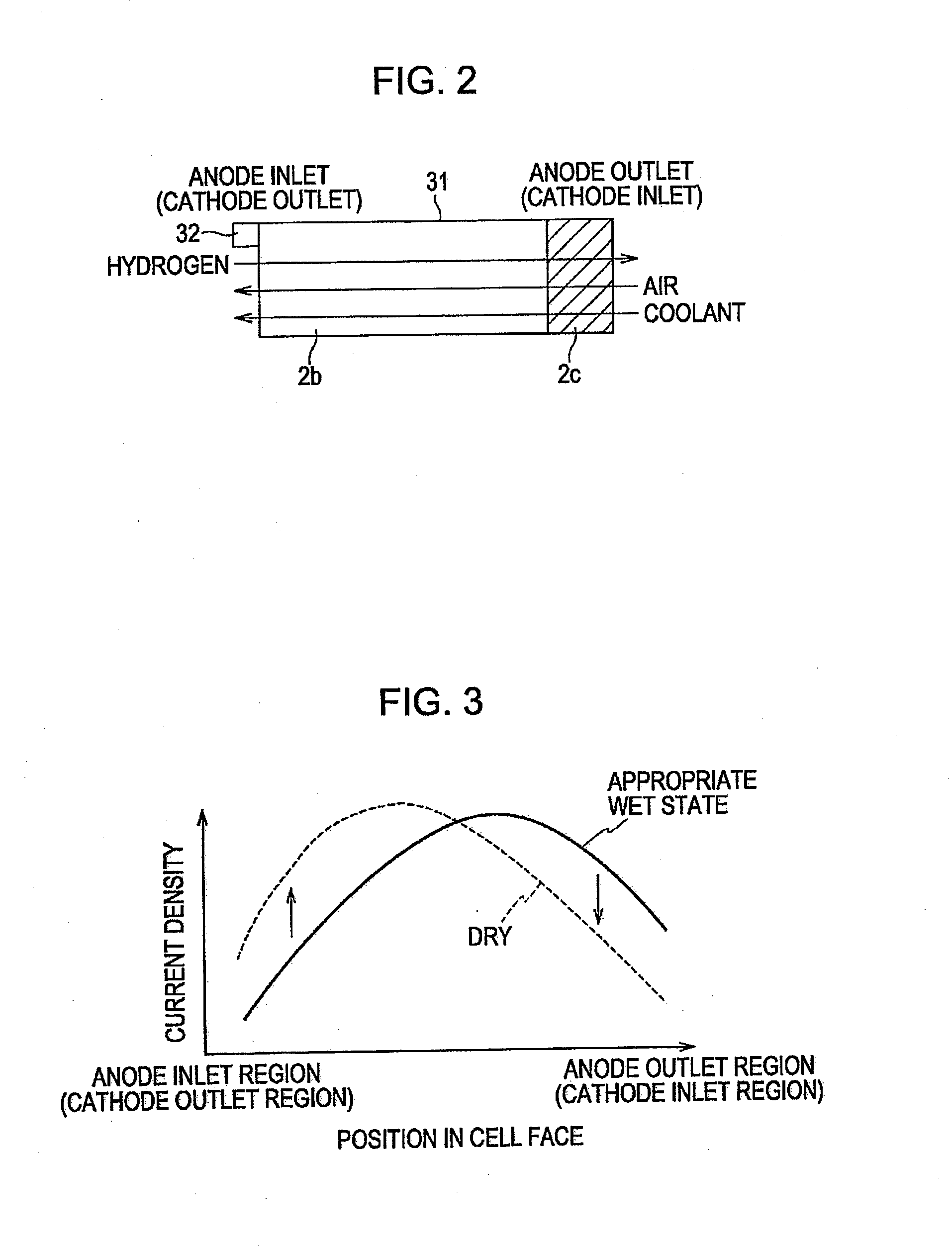
[0028]When fuel cells are employed as power sources of automobiles, the humidifying system is simplified to minimize the size of the fuel cell system. The humidifying performance of the fuel cell system is sufficient at the designed operating point, however, under operation conditions beyond the designed operating point, e.g., at a temperature higher than the designed operating temperature, the solid polymer electrolyte membrane becomes dry (i.e. insufficiently wet). If the membrane is excessively dried, problematic holes will form in the membrane.

[0029]In contrast, when the operating temperature of the fuel cell stack is low, such as when the vehicle is started, the amount of water that can be taken out from the cathode or anode gas channel in the cell face is small, resulting in a high incidence of water-clogging (i.e. excessive wetting) in the cathode and anode channels. Moreover, even after the operation temperature is elevated to a sufficient level, the amount of water generate...


PUM

PropertyMeasurementUnit
cell voltageaaaaaaaaaa
total voltage detectoraaaaaaaaaa
total voltageaaaaaaaaaa

Abstract

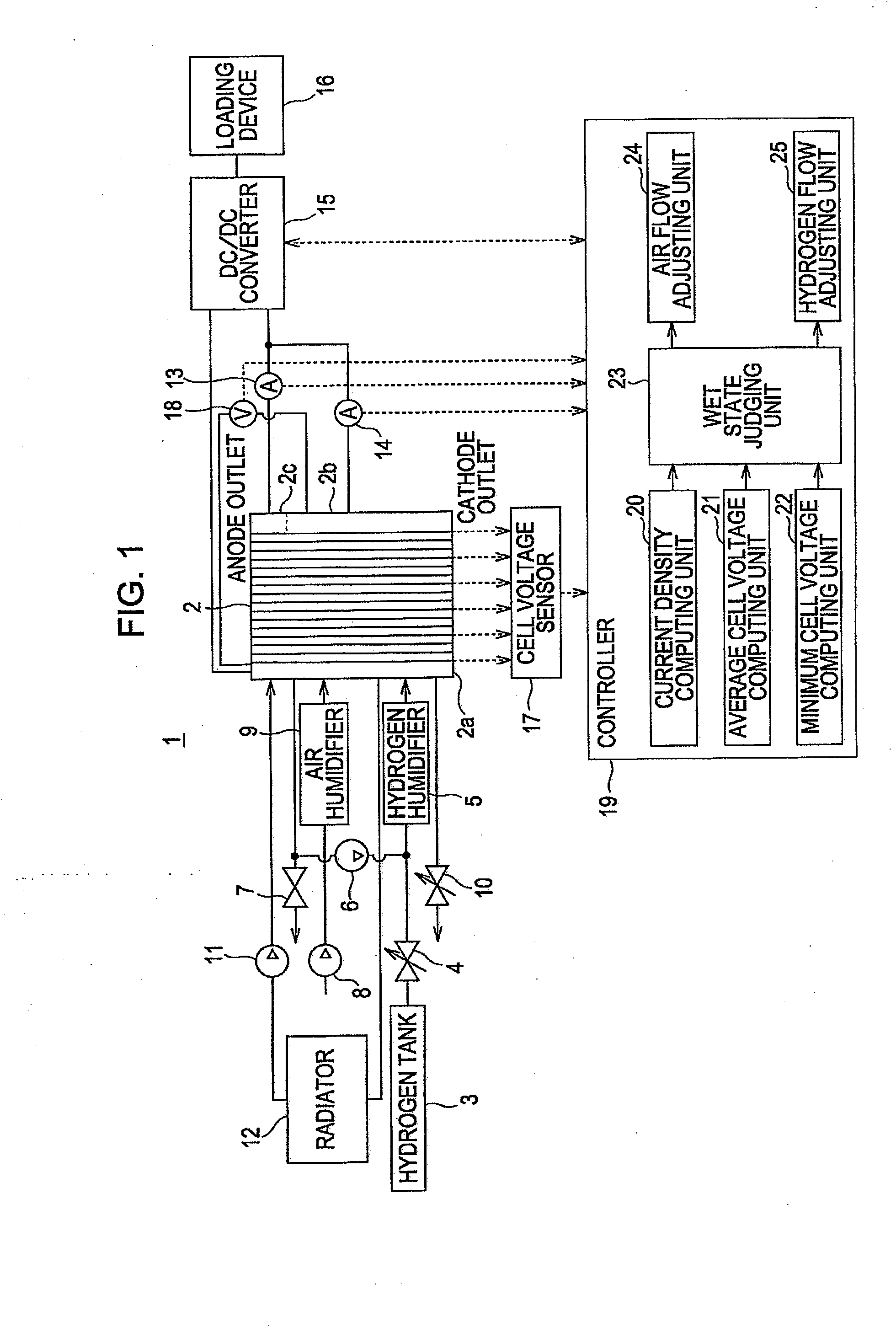
A fuel cell system including a fuel cell stack having a plurality of single cells stacked on one another, each single cell including an anode to which fuel gas can be supplied, a cathode to which oxidizing gas can be supplied, and a solid polymer electrolyte membrane interposed between the anode and the cathode. The oxidizing gas and the fuel gas are configured for counter-flow with respect to each other. A cell voltage detector detects a cell voltage at a cathode outlet-side of a single cell. A total voltage detector detects a total voltage of the fuel cell stack. A cell voltage difference computing unit is configured to determine an average cell voltage from the total cell voltage detector and a minimum cell voltage from the cell voltage detector and to compute a difference between the average cell voltage and the minimum cell voltage. A stack current detector detects electric current in the fuel cell stack. An anode outlet local current detector detects a local current at an anode outlet-side of the fuel cell stack. A current density-computing unit is configured to compute a stack current density from the stack current detector and an anode outlet local current density from the anode outlet local current detector. A wet state-judging unit is configured to judge a wet state of the fuel cell stack based on the difference between the average cell voltage and the minimum cell voltage, and based on the difference between the stack current density and the anode outlet local current density.

Description

CROSS-REFERENCE TO RELATED APPLICATIONS[0001]This application claims priority to Japanese Patent Application No. 2006-218459, filed Aug. 10, 2006, the disclosure of which is incorporated by reference in its entirety.BACKGROUND OF THE INVENTION[0002]1. Field of the Invention[0003]The present invention generally relates to fuel cell systems and particularly to a fuel cell system including a solid polymer electrolyte membrane.[0004]2. Description of the Related Art[0005]In an existing fuel cell system disclosed, for example, in Japanese Unexamined Patent Application Publication No. 2005-228688, in order to judge the wet state of proton-exchange membrane (PEM) fuel cells, operation conditions that affect loads on the fuel cell (e.g., the amount of air flow) are changed to decrease the amount of water in the fuel cell.[0006]When the minimum cell voltage has exceeded a first predetermined value, it is judged that water-clogging has occurred.[0007]In the existing fuel cell system, the cath...

Claims


Application Information

Patent Timeline
Patent Type & Authority Applications(United States)
IPC IPC(8): H01M8/04H01M8/10
CPCH01M8/04179H01M8/04492H01M8/04529H01M8/04552H01M8/04559Y02E60/50H01M8/04589H01M8/04753H01M8/04761H01M8/04992H01M2008/1095H01M8/04582
Inventor KAITO, TAKAHIRO
Owner NISSAN MOTOR CO LTD
Learn More