
System and method for cardiovascular exercise stress MRI

Inactive Publication Date: 2009-10-15
THE OHIO STATES UNIV
View PDF13 Cites 23 Cited by
  • Summary
  • Abstract
  • Description
  • Claims
  • Application Information

AI Technical Summary

Benefits of technology

[0014]Exemplary embodiments of the present invention include a system and method for cardiovascular exercise stress magnetic resonance using a MRI-compatible treadmill and real-time imaging. The MRI-compatible treadmill is positioned directly adjacent to the MRI scan table, enabling configuration of the MRI scan room similar to a stress-echocardiography lab. The configuration allows for exercise CMR that is safe and successful in typical patients requiring cardiac stress testing. A MRI-compatible treadmill allows for the patient to dismount the treadmill and to move immediately onto the scanner table. This approach allows acquisition of images as quickly as possible post-exercise in order to capture transient exercise-induced wall motion abnormalities (WMAs) that can rapidly resolve after ischemia is reversed. The persistence of WMAs is most likely related to the severity of coronary artery disease (CAD) (number of vessels involved, percent stenosis), the presence of coronary collateral flow, and the duration of ischemia. Therefore, in order to accurately diagnose patients with less severe single-vessel CAD, associated with a high ischemic threshold and rapid WMA resolution, imaging performed as close as possible to peak exercise, and ideally with no delay is preferable. Minimizing the time between the end of exercise and the beginning of imaging maximizes the sensitivity of the test.
[0016]The use of MRI-compatible equipment that allows the positioning of the exercise stress system immediately adjacent to the MRI system, and the use of rapid real-time imaging techniques eliminating breath-hold requirements allows exercise stress MRI to be successfully performed in cardiac patients, and has the potential to achieve higher levels of diagnostic accuracy than previously shown for MRI or other stress imaging modalities.

Problems solved by technology

A treadmill positioned any distance from the MRI table, whether inside or outside the room, creates a potential safety concern.
Immediately following maximal exercise patients may become dizzy and lightheaded and subject to falling.

Method used


Image

  • System and method for cardiovascular exercise stress MRI
  • System and method for cardiovascular exercise stress MRI
  • System and method for cardiovascular exercise stress MRI

Examples


Embodiment Construction

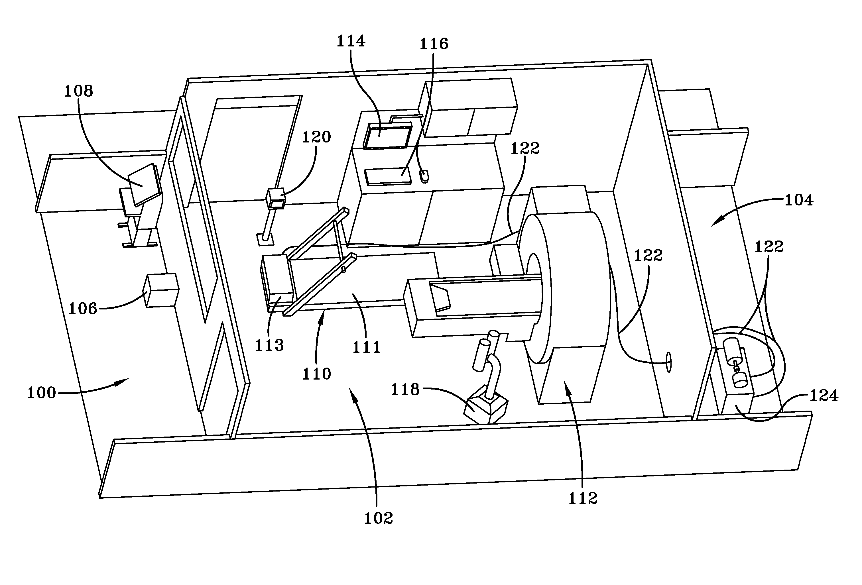
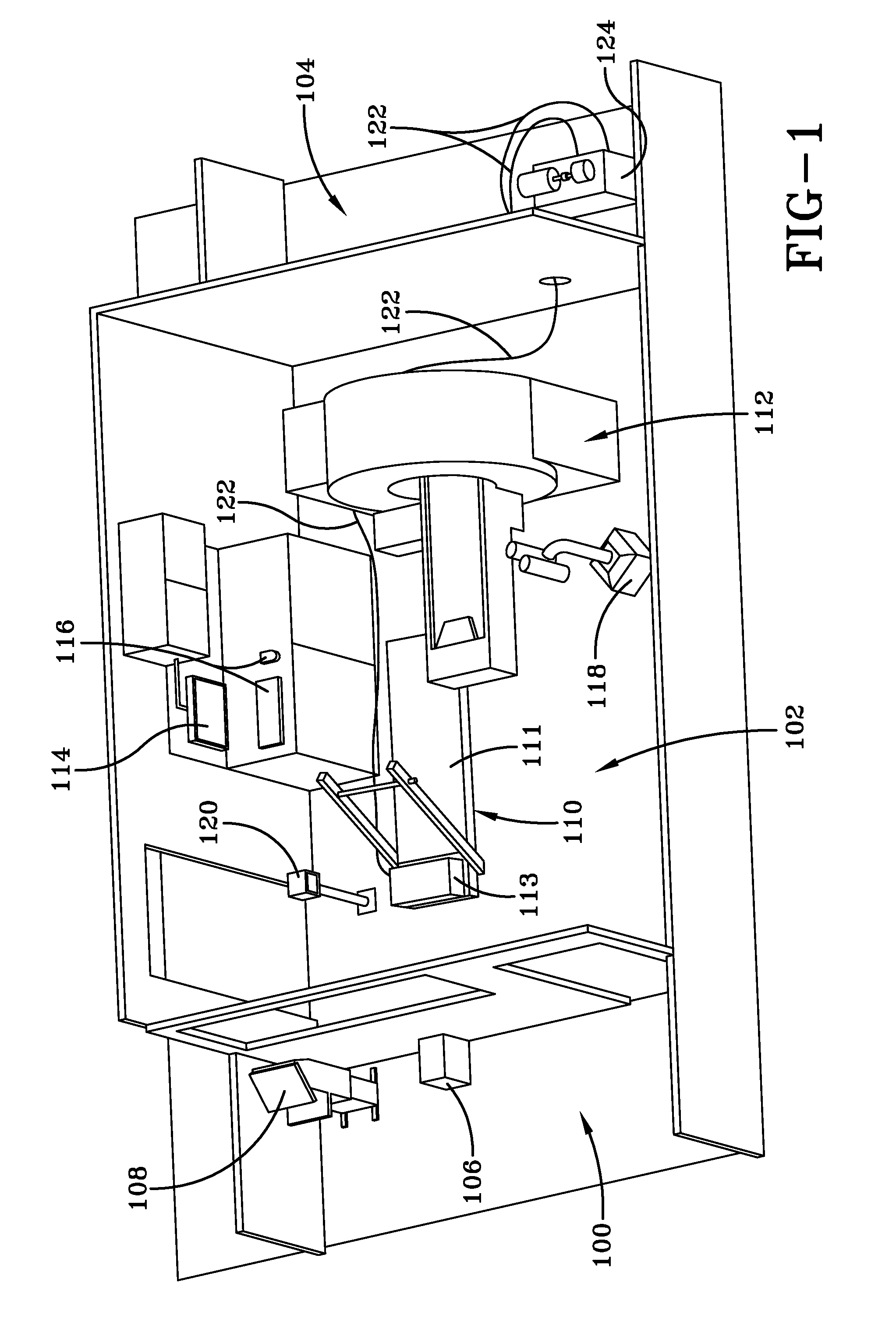
[0025]Referring to FIG. 1, an illustration of components and the configuration of components for a MRI-compatible treadmill system according to an example embodiment of the present invention is shown. In this example, components of the present invention are contained in a control room 100, a scan room 102 and an equipment room 104. One or more computers 106 in the control room 100 support control and monitoring of components in the scan room 102. A treadmill control system computer may be used to communicate with the treadmill 110. Another scanner computer may be used to communicate with the MRI scanner 112. The scanner computer may be used to control functionality of the MRI scanner 112 related to data acquisition, image reconstruction, and image display and analysis.

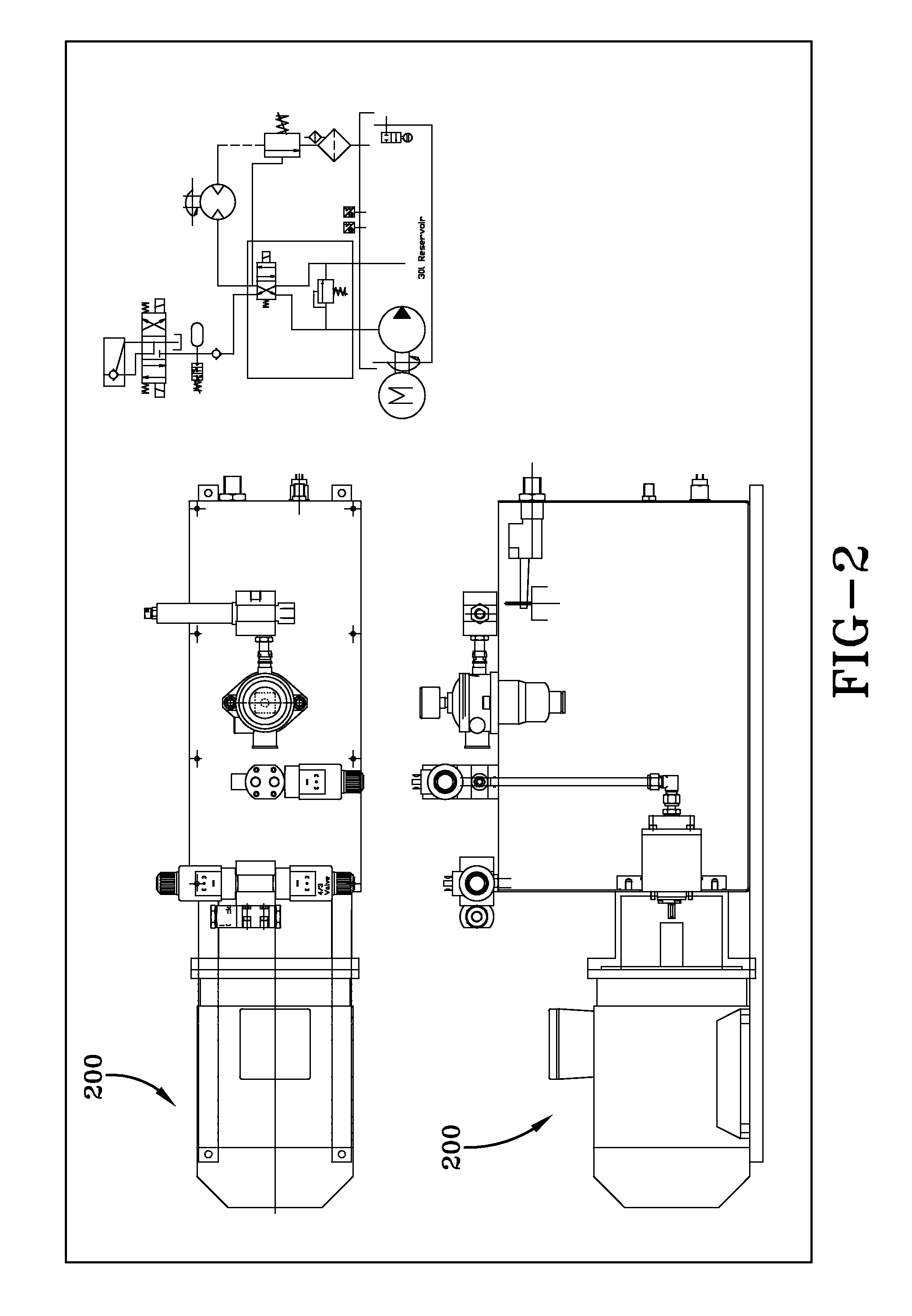
[0026]A hydraulic powered treadmill 110 and MRI scanner 112 are contained in the scan room 102. The hydraulic powered treadmill 110 is connected to a hydraulic power pack 124 via hydraulic hoses 122. In FIG. 1, certain...


PUM


Abstract

A system and method for cardiovascular exercise stress magnetic resonance using a MRI-compatible treadmill and real-time imaging. The treadmill comprises non-ferromagnetic components so that it may be used in proximity to a MRI scanner. The treadmill is positioned adjacent to the MRI scan table. A treadmill control system is used to control the speed and grade of the treadmill to allow it to perform a wide range of exercise protocols. Patients complete an exercise protocol on the treadmill and are then moved to the MRI scan table. Images are acquired as quickly as possible post-exercise to more accurately diagnose cardiovascular disease in patients.

Description

CROSS-REFERENCE TO RELATED APPLICATIONS[0001]This application is a continuation under 35 USC §120 of PCT / US2007 / 081948, filed Oct. 19, 2007, titled SYSTEM AND METHOD FOR CARDIOVASCULAR EXERCISE STRESS MRI, which is in turn entitled to benefit of a right of priority under 35 USC §119 from U.S. Ser. No. 60 / 862,107, filed Oct. 19, 2006, titled MAGNETIC RESONANCE COMPATIBLE TREADMILL, both of which are herein incorporated by reference in their entirety.TECHNICAL FIELD[0002]Exemplary embodiments of the present invention relate to systems and methods for cardiovascular magnetic resonance imaging. More particularly, one exemplary embodiment of the present invention is a system and method for cardiovascular magnetic resonance imaging using exercise stress.BACKGROUND OF THE INVENTION[0003]Since it was first proposed as a diagnostic tool for angina almost 75 years ago, treadmill exercise stress testing quickly became, and still remains, an essential tool in the detection and treatment of hear...

Claims


Application Information

Patent Timeline
IPC IPC(8): A61B5/055A63B22/02
CPCA61B5/0046A61B5/055A61B5/222A61B5/02A63B21/158A63B22/02A61B5/0044A61B5/4884
Inventor SIMONETTI, ORLANDO PAULFOSTER, ERIC LEEARNOLD, JOHN WAYNERAMAN, SUBHA V.
Owner THE OHIO STATES UNIV
Learn More