Reamer for Operating Implant

a technology for operating implants and reamers, which is applied in the field of reamer for operating implants, can solve the problems of prolonging the treatment period, difficult to operate the upper molar implant, and taking a long time to ossify the grafted bone, etc., and achieves the effect of convenient and safe operation

Inactive Publication Date: 2009-10-15
AHN IN
View PDF6 Cites 26 Cited by
  • Summary
  • Abstract
  • Description
  • Claims
  • Application Information

AI Technical Summary

Benefits of technology

[0016]Accordingly, the present invention has been made to solve the above-mentioned problems occurring in the prior art, and it is an object of the present invention to provide a reamer for operating an implant, which includes a horizontal cut edge, a protruding face and a depressed face formed on the upper end of a cutting part, thereby allowing a dentist to perform a bone graft between a mucosa of the maxillary sinus and a bone more easily and safely without any damage of the mucosa of the maxillary sinus.

Problems solved by technology

That is, the maxillary sinus existing in the upper molar part is a space surrounded with a mucosa, and so, since it physiologically comes down and is expanded when a tooth is lost, the maxillary sinus is short of bone quantity for planting the implant thereto due to a bone absorption and the downward expansion of the maxillary sinus when the tooth is lost, whereby it is difficult to operate the implant in the upper molar part.
However, the lateral window sinus lift has a problem in that it takes much time to ossify the grafted bone and a treatment period of time is extended since the operation is difficult and a great deal of bones are grafted.
However, since the twist drill used for the operation has a number of sharp blades and a peaked conical upper end, it is good to a forward cutting of the bone, but has a problem in that skilled and unskilled dentists all feel difficulty in forming the hole for planting the implant in the compact bone using the drill without any damage to the mucosa of the maxillary sinus.
That is, since the drill has the peaked conical upper end, when the upper end of the drill is in contact with the mucosa of the maxillary sinus during rotation, a vertical force is concentrated on the mucosa of the maxillary sinus, which is in point contact with the upper end of the drill, so that the mucosa of the maxillary sinus is easily ruptured and it is difficult to keep and hold the bone graft material for formation of the bone, whereby an infection rate is increased since the implant is not located inside the bone but exists inside the maxillary sinus in an exposed state.
In addition, the internal sinus lift has another problem in that a force to hold and support the implant is deteriorated since the bone quantity is small.
So, no matter how careful the dentist may hit the osteotome, since such operation skill can be obtained by a fine sense of the dentist's hand through abundant operation experiences, not only dentists who have no abundant operation experiences but also dentists who have abundant operation experiences had a difficulty in operation since the mucosa of the maxillary sinus is flatly ruptured when the dentist hits the osteotome a little strongly due to misadjustment of the force.
Furthermore, since the compact bone is fractured in irregular sizes and it is impossible to form the hole of a wanted type, it is impossible to obtain an initial fixation of the screw type implant into a cortical bone which is short of the remaining bone.

Method used


Image

  • Reamer for Operating Implant
  • Reamer for Operating Implant
  • Reamer for Operating Implant

Examples


Embodiment Construction

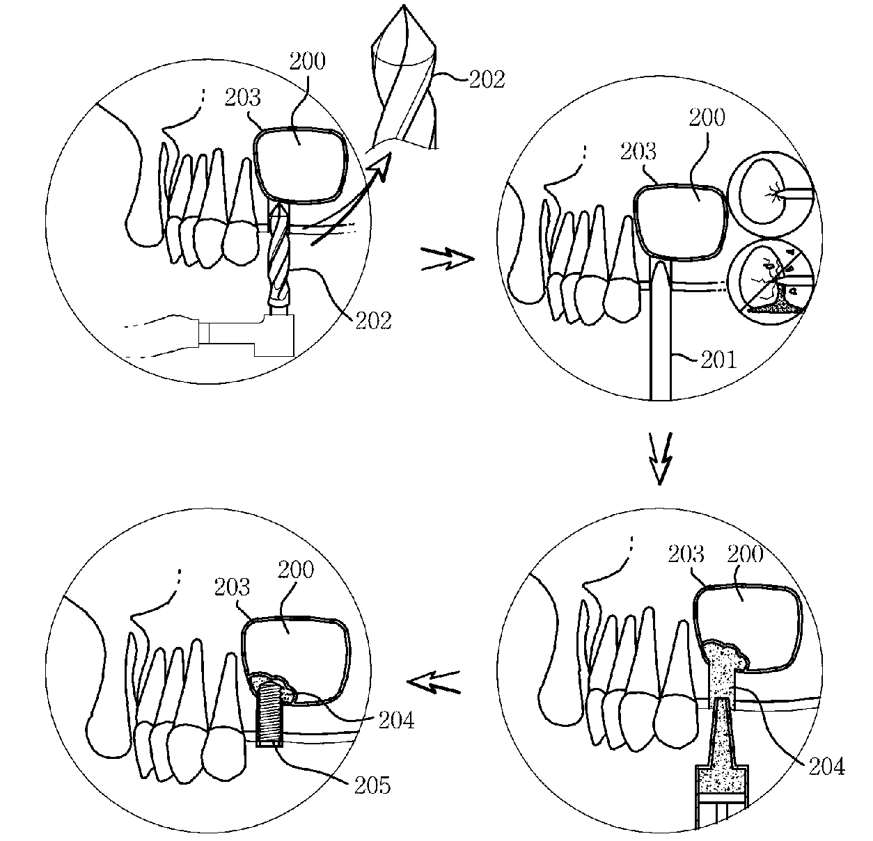
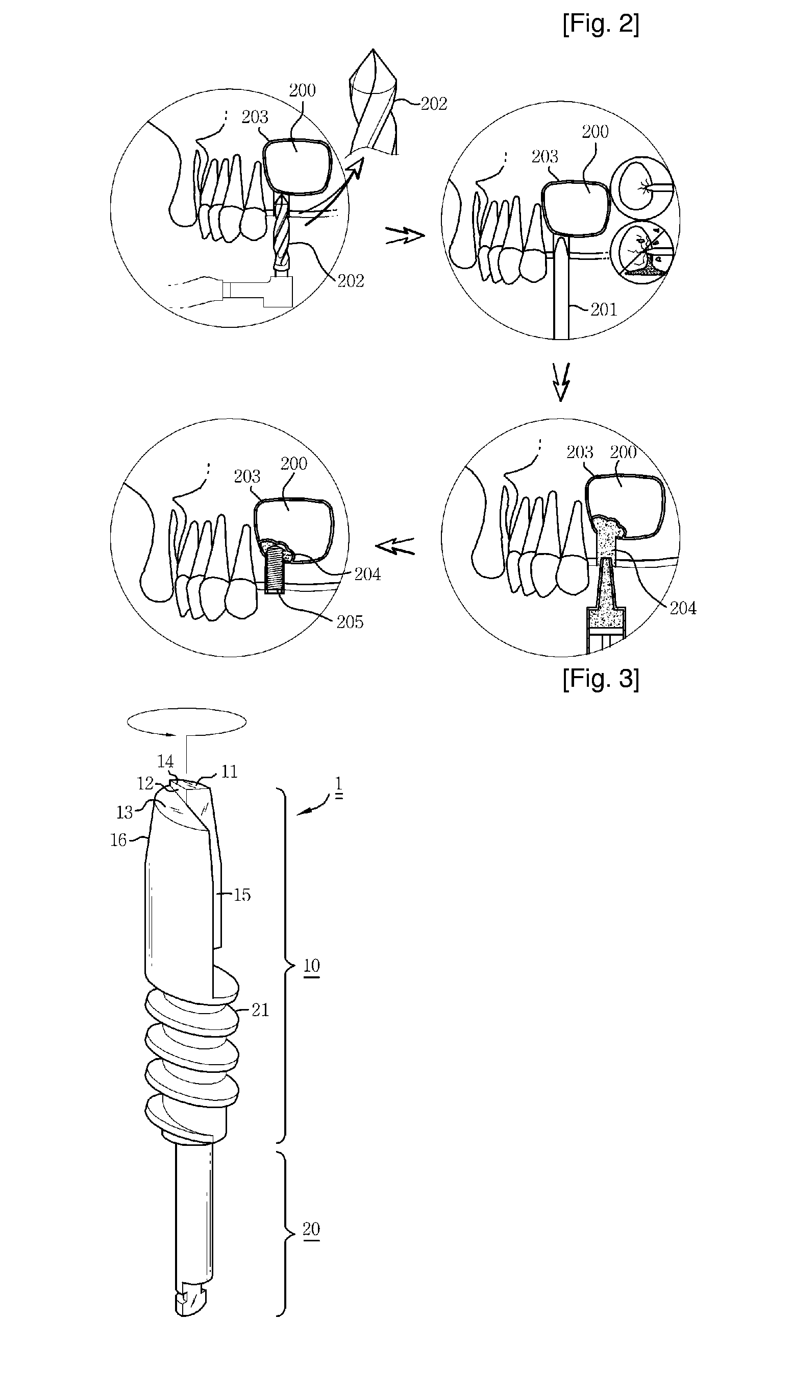
[0039]FIG. 3 is a perspective view of a reamer according to a preferred embodiment of the present invention, FIG. 4 is a partially enlarged view of the reamer according to the present invention, FIG. 5 is a view showing an implant operating process of the reamer according to the present invention, and FIG. 6 is a comparative view showing a state where a drill and the reamer are used according to the present invention. Hereinafter, reference will now be made in detail to the preferred embodiments of the present invention, examples of which are illustrated in the accompanying drawings.

[0040]As shown in FIGS. 3 and 4, the reamer 1 according to the present invention includes a cutting part 10 for forming a hole 33 for planting an implant 34 in a bone 32, and a connection part 20 extending from the bottom side of the cutting part 10 and having a diameter smaller than that of the cutting part 10.

[0041]The cutting part 10 is in the form of a cylinder having a predetermined diameter, and th...


PUM


Abstract

Disclosed therein is a reamer for operating implant, which can very usefully apply an implant operation to a patient who is short of bone quantity to the maxillary sinus, which is easier and safer than a conventional hammering method using a drill and an osteotome or a conventional operation method for transplanting a bone or planting an implant after forming a bone window on a maxillary sinus side wall, and which can reduce a treatment time period and treatment costs by minimizing the patient's pain occurring before and after the operation of the implant. A cutting part of the reamer includes: a protruding face formed on the top surface thereof in such a manner as to upwardly upheave a partial surface including an outer circumference of the cutting part of the entire top surface of the cutting part to form a stepped jaw; a depressed face formed on the top surface thereof in such a manner as to depress a partial surface of the entire top surface of the cutting part to be opposite to the protruding face according to the formation of the protruding face, the depressed face having a reverse inclination in a clockwise direction; a cut edge horizontally formed on a connected portion between the stepped jaw and the protruding face so that the cut edge evenly disperses a force while being in horizontal line contact with the mucosa even though the cut edge is in contact with the mucosa of the maxillary sinus so as to allow a dentist to perform a cutting work safely without damaging a mucosa of a maxillary sinus; and a discharge path longitudinally formed on the cutting part in such a manner as to cut an area ranging from a partial surface of the top surface of the cutting part, i.e., a predetermined portion between the protruding face and the depressed face to a portion which is slightly shorter than the lower end of the cutting part.

Description

TECHNICAL FIELD[0001]The present invention relates to a reamer for operating implant, which is adapted to form a hole in a bone to plant an implant during a dental implant operation, and more particularly, to a reamer for operating implant, which can very usefully apply an implant operation to a patient who is short of bone quantity of up to the maxillary sinus, which is easier and safer than a conventional hammering method using a drill and an osteotome or a conventional operation method for transplanting a bone or planting an implant after forming a bone window on a maxillary sinus side wall, and which can reduce a treatment time period and treatment costs by minimizing the patient's pain occurring before and after the operation of the implant.BACKGROUND ART[0002]In general, an implant originally means a replacement for recovering lost body tissues when tissues of the human body are lost, but means a transplantation of an artificial tooth in a dental surgical field.[0003]The impla...

Claims


Application Information

Patent Timeline
Patent Type & Authority Applications(United States)
IPC IPC(8): A61B17/00
CPCA61C8/0006A61C8/0092A61C8/0089A61C1/00A61C8/00
Inventor AHN
Owner AHN IN
Why Eureka
Try Eureka