Unlock instant, AI-driven research and patent intelligence for your innovation.
Track transportation system
Active Publication Date: 2009-10-15
MITSUBISHI HEAVY IND ENG LTD
View PDF11 Cites 19 Cited by
Summary
Abstract
Description
Claims
Application Information
AI Technical Summary
This helps you quickly interpret patents by identifying the three key elements:
Problems solved by technology
Method used
Benefits of technology
Benefits of technology
[0021]The present invention is contrived in consideration of the above-described problems, and an object of the invention is to provide a track transportation system in which a vehicle runs on a predetermined truck, being automatically steered, having a simplified and lightweight structure so as to surely ensure a safety, and to be capable of carrying out efficient and high-speed operation without using a mechanical steering mechanism such as guide wheels and a guide rail.
Problems solved by technology
However, the above-mentioned mechanical guide mechanisms which are though excellent in safety and reliability, cause the configuration of a bogie of a vehicle, on which wheels and drive mechanism are mounted, to be complicated, and as a result, the mass and the running costs of the vehicle are increased, and further, a guide rail having a strength which is sufficient for supporting the guide wheels, should be laid with a high degree of accuracy over the entire length of a track, resulting in the disadvantages that the construction costs of the track becomes extremely high.
However, the steering system disclosed in the Patent Document 3 does not use a mechanical steering mechanism including guide wheels and a guide rail, and accordingly, requires safety measures for protection against runaway or come-off of the vehicle from the track in the case of a failure of the steering system or emergency caused by environment disturbance, that is, strong wind, rain, snow or the like.
The above-mentioned conventional track transportation system has been insufficient for ensuring the safety compensating a deviation of a running position with a simple and lightweight configuration, and also capable of diving at a high speed with a high degree of accuracy.
Method used
Image
Click on the blue label to locate the original text in one second.
Reading with bidirectional positioning of images and text.
Examples
embodiment 1
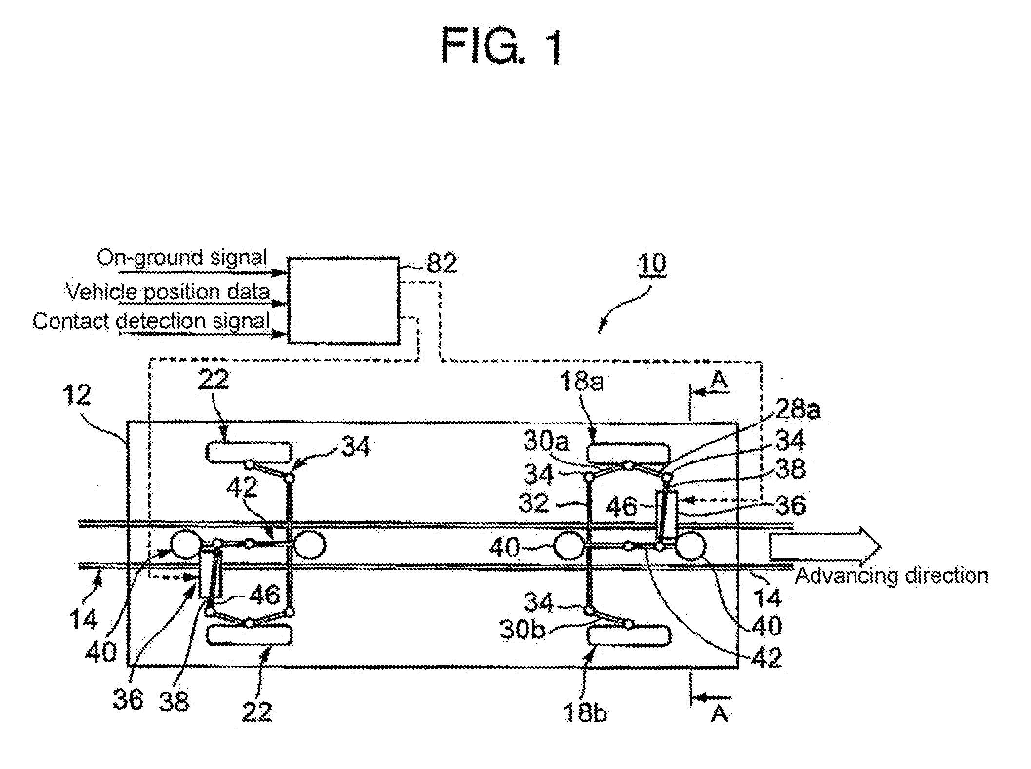
[0080]FIGS. 1 to 8 show a first embodiment of the present invention. As shown in FIGS. 1 and 2, a track transportation system 10 incorporates a vehicle 12 which runs on a track 01. The track 01 is provided in its substantially widthwise center section with a U-like sectional shape protection guide rail 14 which is channel-like with respect to a road surface 15. That is, a U-like steel bar is laid so as to form the U-like protection guide rail 14.
[0081]The vehicle 12 is provided thereunderneath with a front wheel bogie 16 for supporting the vehicle 12 and a rear wheel bogie (which is not shown), respectively in the front and rear portion thereof. The front wheel bogie 16 is mounted thereto with an axle for front wheels 18, which is turnable left and right. The front wheels 18 are worn thereon with core type rubber tires 20 which are not shown. Further, the rear wheel bogie is also mounted thereto with an axle for rear wheels 22, which is turnable left and light. The rear wheels 22 ar...
embodiment 2
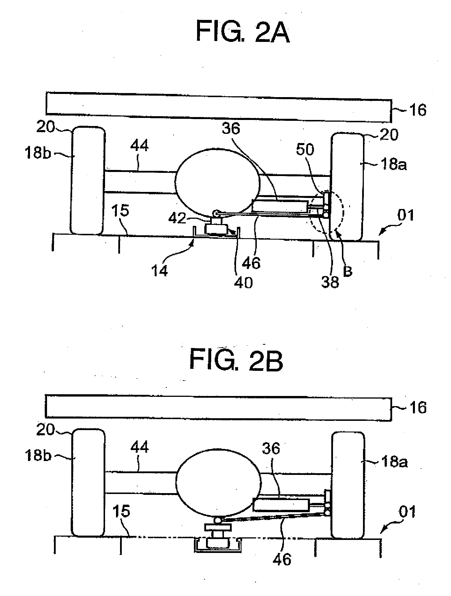
[0124]Next, a second embodiment of the present invention will be explained with reference to FIGS. 9 to 10. The second embodiment will concern a variant form of the steering mechanism 25 explained in the first embodiment. Like reference numerals will be used to denote parts like to those explained in the first embodiment so as to abbreviate the explanation thereto.
[0125]Referring to FIG. 9 which is a plane view, the basic configuration of the steering mechanism 26 is identical to that explained in the first embodiment, except that the link rod 46 is located on the side remote from the place where the actuator 36 is arranged.
[0126]Although both left and right spaces are occupied, this arrangement is effective in the case that both link rod 46 and actuator 36 cannot be arranged one upon another on one side due to the actuator 36 having a large size. Further, since the necessity of a component such as the twin spherical surface joint 50 used in the first embodiment can be eliminated, t...
embodiment 3
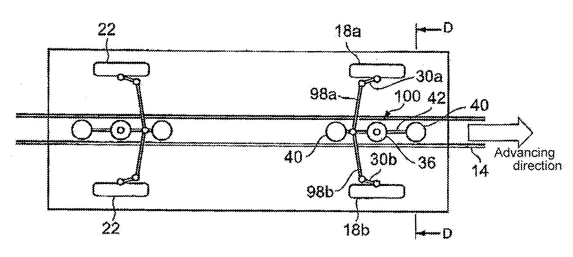
[0127]Next, explanation will be made of a third embodiment of the present invention with reference to FIGS. 11 and 12. The third embodiment will concern a variant form of the steering mechanism 26.
[0128]Referring to FIGS. 11 and 12, the rear end part of the protection arm 42 and the rear end parts of the rear steering arms 30a, 30b for the left and right wheels are connected to one another by means of left and right side tie rods 98a, 98b, and the respective connection parts are constituted by spherical joints 34. Further, the actuator 36 is coupled to the rear end part of the protection arm 42 which is therefore turned directly thereby. It is noted that a linear motor or the like may be used as the actuator 36.
[0129]In this embodiment, since the protection arm 42 is directly operated by the actuator 36, backlash caused by abrasion of a rod end or a rotary part or bending of a rod can be prevented, thereby it is possible to reduce control delay or control error, resulting in accurat...
PUM
Abstract
The essential feature of the present invention is the provision of a track transportation system in which a vehicle runs on a predetermined track, being automatically steered, having a simplified and lightweight structure so as to surely ensure a safety, and to be capable of carrying out efficient and high-speed operation. The track transportation system according to the present invention incorporates a steering mechanism for automatic steering by means of an M actuator, a protection guide rail laid on the track, protection guide wheels which travel together with the vehicle along the protection guide rail without making contact with the latter, and a control means for controlling automatic steering in accordance with a result of determination by a track data determining means for determining a straight portion, a curved portion, a turnout portion or the like of the track in view of vehicle position data, and steering caused by the protection wheels making contact with the protection guide rail.
Description
RELATED APPLICATIONS[0001]The present application is based on, and claims priority from, International Application Number PCT / JP2006 / 322403, filed Nov. 1, 2006, the disclosure of which is hereby incorporated by reference herein in its entirety.TECHNICAL FIELD[0002]The present invention relates to a transportation system for a vehicle which runs on a predetermined track by means of, for example, running wheels of a rubber tire type.BACKGROUND ART[0003]A vehicle in new transportation system, having rubber tires which carries a vehicle body and which are adapted to be driven for rotation so as to run the vehicle, is different from a railway vehicle running on rails, and is normally provided with steering guide wheels for steering the rubber tires serving as running wheels along a predetermined track. Accordingly, the guide wheels make contact with a guide rail provided along the track in order to mechanically steer the vehicle.[0004]For example, Patent Document 1 (Japanese Patent Laid-...
Claims
Application Information
Patent Timeline
Application Date:The date an application was filed.
Publication Date:The date a patent or application was officially published.
First Publication Date:The earliest publication date of a patent with the same application number.
Issue Date:Publication date of the patent grant document.
PCT Entry Date:The Entry date of PCT National Phase.
Estimated Expiry Date:The statutory expiry date of a patent right according to the Patent Law, and it is the longest term of protection that the patent right can achieve without the termination of the patent right due to other reasons(Term extension factor has been taken into account ).
Invalid Date:Actual expiry date is based on effective date or publication date of legal transaction data of invalid patent.

