
Drive system of a forming press

a technology of forming press and drive system, which is applied in the direction of presses, belts/chains/gearrings, manufacturing tools, etc., to achieve the effect of reducing technical complexity and high pressing for

Inactive Publication Date: 2009-10-22
MASCHFAB MULLER WEINGARTEN AG
View PDF15 Cites 22 Cited by
  • Summary
  • Abstract
  • Description
  • Claims
  • Application Information

AI Technical Summary

Benefits of technology

[0017]The underlying object of the invention is to configure a drive system for a multi-point forming press such that on the one hand high pressing forces can be attained using the available torques of servo-motors and on the other hand to reduce the technical complexity both in the design of the drive having a plurality of mechanically synchronized pressure points and also in the design of the drive having pressure points that can be controlled independent of one another. The intent of the latter design is in particular spatial tilt control for the slide in two planes when using a forming press embodied with four pressure points. Moreover, the mechanical and personnel safety requirements for the press that can be controlled by one or a plurality of servo-motors are to be satisfied.
[0024]In one advantageous embodiment, axially displacing these intermediate gears and the associated pinion can select and deselect the mechanical link between the pressure points.
[0029]For further reducing the drive torque it is possible to arrange between the crank wheels and pressure points of the slide a lever mechanism that creates a transmission.

Problems solved by technology

Moreover, it is conceivable to use a single gear transmission to drive separately crank wheels jointly allocated to the two pressure point groups of a four-point press so that tilt control for the slide is only possible in one plane.

Method used


Image

  • Drive system of a forming press
  • Drive system of a forming press
  • Drive system of a forming press

Examples


Embodiment Construction

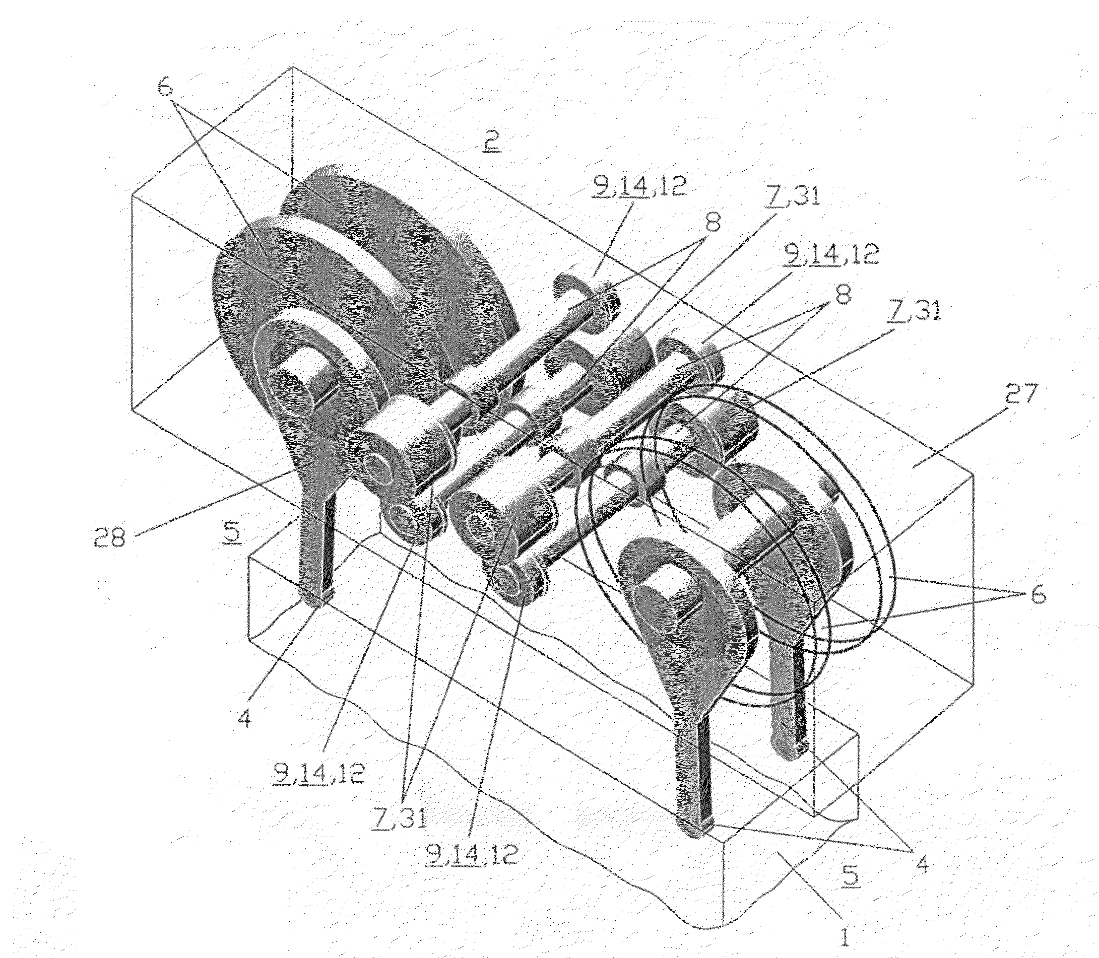
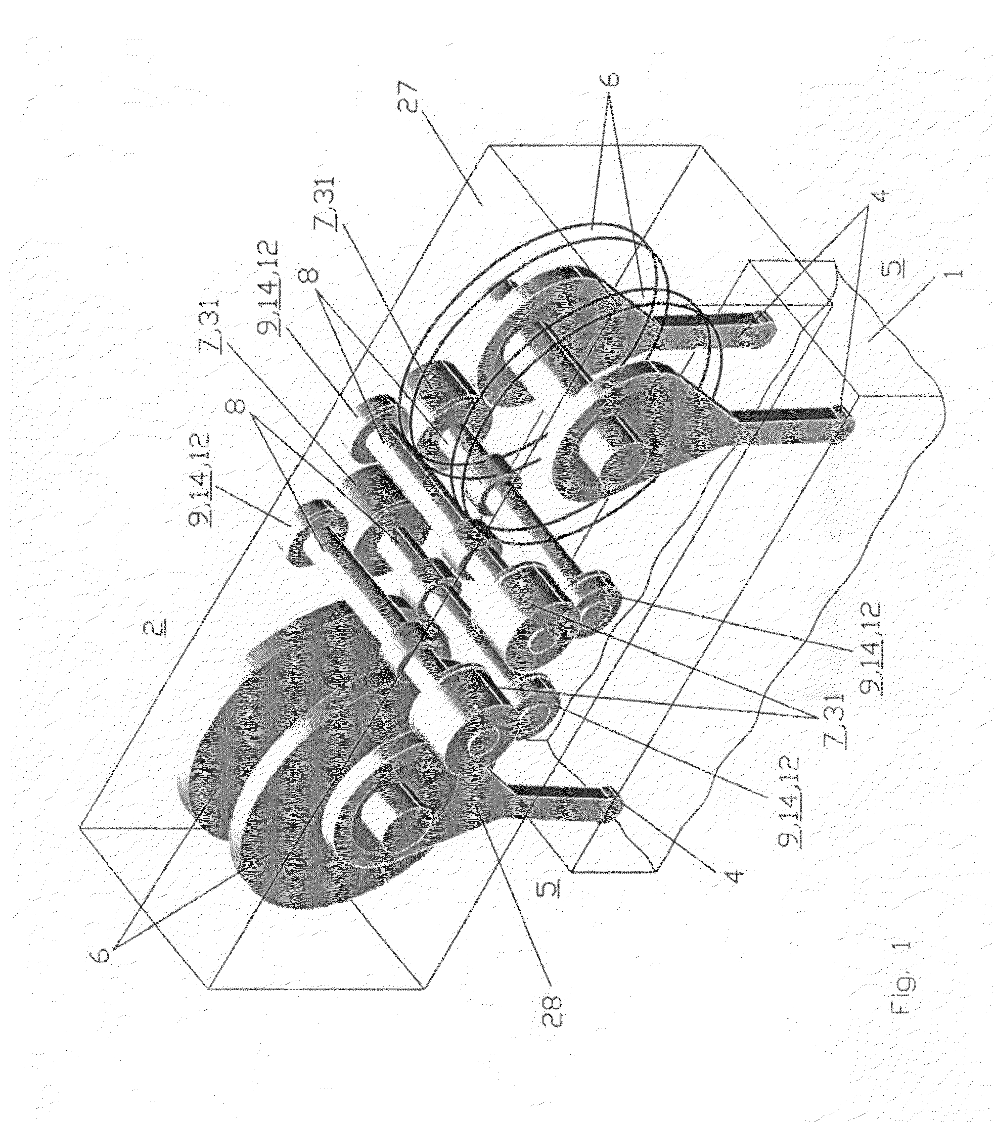
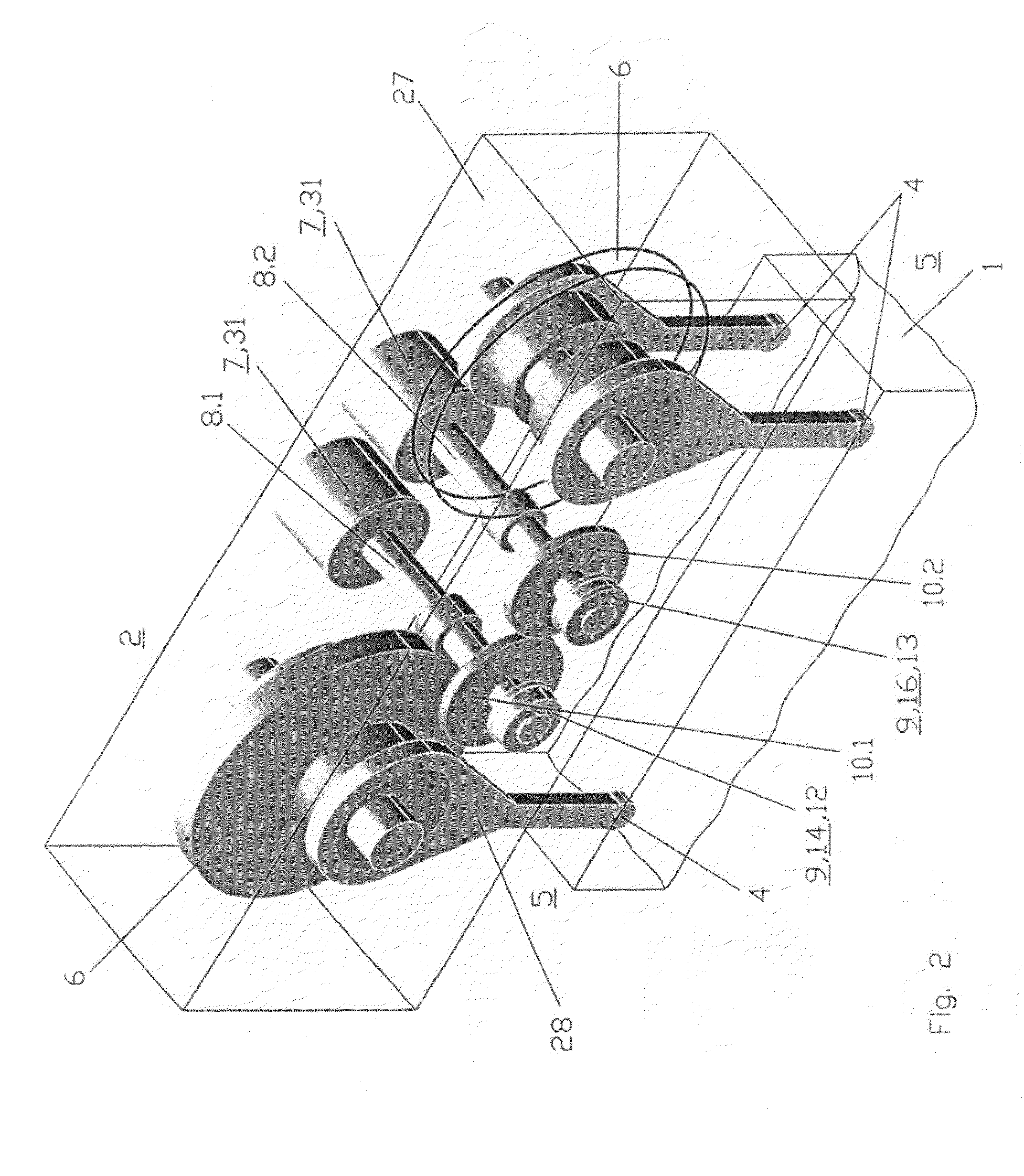
[0049]In a first exemplary embodiment of the first design type, FIG. 1 depicts a four-point forming press, the drive 2 of which occurs on the four pressure points 4 of the slide 1 by means of a crank mechanism 3, each pressure point 4 being driven separately. The crank mechanism 3 for each pressure point 4 comprises a crank wheel 6 that is borne in the head piece 27 and that is connected on the output side via an eccentrically attached connecting rod 28 to the pressure point 4 of the slide 1 and on the drive side to a first pinion shaft 8. In the second exemplary embodiment of the first design type in accordance with FIG. 13, a common crank wheel 6 that is connected on the drive side to a first pinion shaft 8.1, 8.2 is allocated to the two pressure points 4 in a pressure point group 5. What these two exemplary embodiments have in common is that the first pinion shaft 8 borne in the head piece 27 can be controlled by a freely programmable servo-motor 7 arranged at the first shaft end...


PUM


Abstract

A drive system of a forming press for driving the plunger with a crank mechanism controllable by a servomotor is refined in such a way that on the one hand a high pressure force is achievable with the available torques of servomotors and that on the other hand the technical complexity of the drive is reduced during the design of the drive with multiple mechanically synchronized pressure points and also with pressure points that can each be controlled independently of one another. The concept of the method consists of transferring the torques of the servomotors that are required to achieve a high pressure force for the plunger by means of intermediate gearing, preferably with a double gear transmission, to the cam or crank mechanism, wherein the symmetrically configured drive arms of multipoint presses for the right and the left pressure points of two-point presses or the pressure point groups of four-point presses are optionally mechanically synchronized with one another in such a way that each of the intermediate gears of the first or of one of the first gear transmissions is effectively connected to the others.

Description

BACKGROUND OF THE INVENTION[0001]The invention relates to a drive system for a multi-point forming press.[0002]Known according to DE 10 2004 009 256 is a mechanical multi-servo-press in which the servo-motors with associated pinions as a single-stage gear at spaced apart locations each drive an eccentric wheel for driving a slide having two pressure points. At great pressing forces, high torques for the servo-motors are necessary due to the limited transmission ratio of the single-stage gear. In this regard, the document discloses that the load on the servo-motors can be reduced by using the momentum of the mass moment of inertia of the gear. Since this effect can only be used at elevated speeds, at low speeds the servo-motors would be underdimensioned for applying the installed pressing force, especially in set-up mode.[0003]The intermediate gears that connect the eccentric wheels and that are also necessary for mechanical synchronization in the gear result in increased complexity....

Claims


Application Information

Patent Timeline
Patent Type & Authority Applications(United States)
IPC IPC(8): B30B1/26
CPCB30B1/266B30B15/10Y10T74/18248B30B15/148B30B15/14B30B15/287
Inventor DARR, UWESCHMIDT, STEFFENGOETZ, EDWINVOEGEL, GERHARDMEINHARDT, WOLFGANG
Owner MASCHFAB MULLER WEINGARTEN AG
Learn More