Method for generating pre-distorted signals

A predistortion signal and generation method technology, applied in the field of linearization, can solve the problems of narrow working bandwidth, poor cancellation effect, low efficiency, etc., and achieve the effect of improving working efficiency and wide working bandwidth

Inactive Publication Date: 2009-12-02
COMBA TELECOM SYST CHINA LTD
View PDF0 Cites 8 Cited by
  • Summary
  • Abstract
  • Description
  • Claims
  • Application Information

AI Technical Summary

Problems solved by technology

[0005] Since the non-constant envelope signal of the modulation technology will cause the power amplifier to produce large nonlinear characteristics, the multi-carrier power amplifier conventionally adopts the feed-forward (FF) technology architecture, although it has excellent cancellation performance, wide operating bandwidth, and multi-standard However, due to factors such as high technical complexity, low efficiency, and high cost, its development is restricted
[0006] Due to the influence of factors such as narrow working bandwidth and poor cancellation effect, analog predistortion technologies such as envelope tracking cannot work in the case of multi-carrier
[0007] Digital predistortion technology is a promising linearization technology, which has the characteristics of high work efficiency and moderate cancellation, but due to the limitation of people's understanding of the nonlinear characteristics of semiconductor devices and the limitations of A / D, D / A. Due to the limitation of the working rate of DSP, the working bandwidth is limited, and its application is subject to certain restrictions.
[0008] In addition, no matter from the perspective of theory or practice, domestic and foreign patent documents related to digital pre-distortion technology all reveal that the complexity of generating digital pre-distortion signals in the prior art is relatively high, and it cannot be adaptively adjusted to adapt to different electrical environments. Therefore, a good linearization technique effect cannot be achieved

Method used


Image

  • Method for generating pre-distorted signals
  • Method for generating pre-distorted signals

Examples


Embodiment Construction

[0026] Below in conjunction with accompanying drawing and embodiment the present invention will be further described:

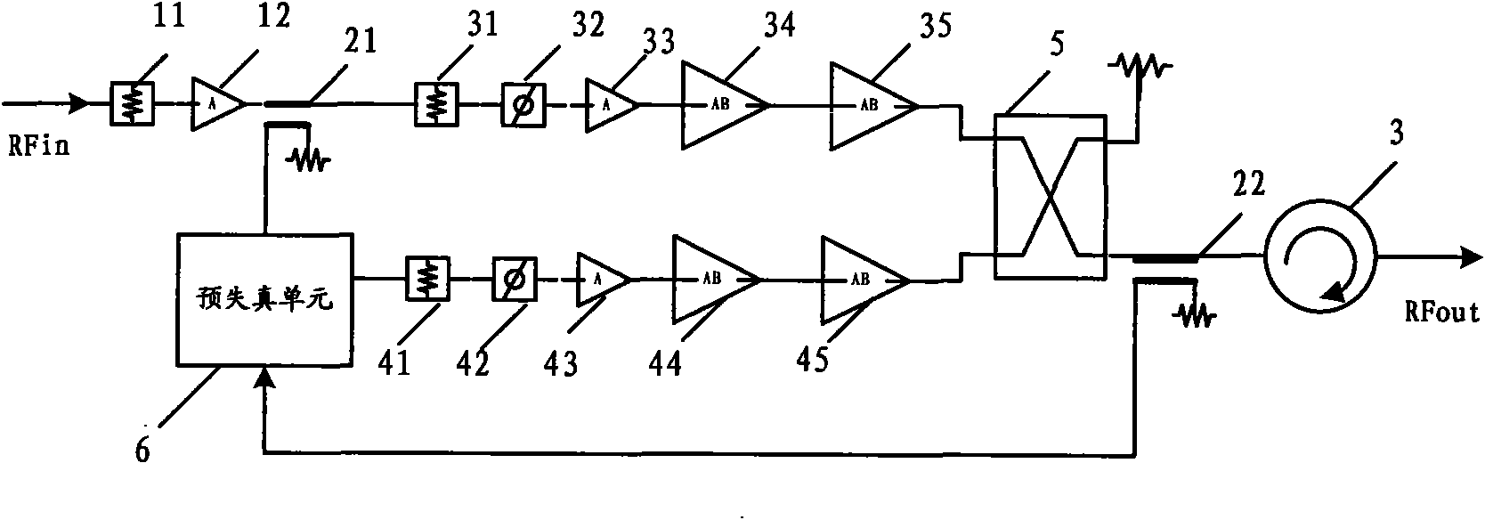
[0027] see figure 1 , which discloses a predistortion radio frequency amplifier realized according to a predistortion signal generation method, this kind of predistortion radio frequency amplifier can be directly used in a mobile communication repeater (not shown), and connected to the uplink and / or downlink, power amplification is performed on uplink signals and / or downlink signals in the radio frequency domain, and the whole process is completely processed in the radio frequency domain without digital processing.

[0028] figure 1 , the direction indicated by the arrow RFin is the input direction of the radio frequency initial carrier signal, and the arrow RFout indicates the output direction of the radio frequency initial carrier signal after being processed by the two links.

[0029] In the predistortion RF amplifier, towards the direction indicated by...


PUM


Abstract

The invention discloses a method for generating pre-distorted signals, used for generating the pre-distorted signals in the radio frequency field for a power amplifier. The method comprises the following steps: coupling an unamplified initial carrier signal with a combined signal mixed with an intermodulation signal during the process of amplifying the initial carrier signal; dividing the initialcarrier signal obtained by coupling into two paths to output after delaying, after combining the initial carrier signal of a first path with the combined signal obtained by coupling to offset mutual carrier signals, obtaining the intermodulation signal, and generating the pre-distorted signal after combining the intermodulation signal with the initial carrier signal of a second path again. The pre-distorted signal comprises the carrier signal and the intermodulation signal, and amplitudes and phases of the two signals can be individually and flexibly adjusted according to demands. The method can realize higher working bandwidth and working efficiency when applied to a pre-distorted radio frequency amplifier and can be applied to different working environments.

Description

【Technical field】 [0001] The invention relates to the technical field of linearization of a power amplifier in a modern mobile communication system, in particular to a method for generating a predistortion signal. 【technical background】 [0002] For a long time, the efficiency improvement technology and the linearization technology of the power amplifier used in the communication system have been the research hotspots in the industry. [0003] Due to the adoption of various non-constant envelope modulation methods (such as QPSK, QAM, OFDM, etc.), modern wireless communication systems have greatly improved the utilization of frequency resources. , 2.5G, 3G, 4G, LTE) are growing rapidly, and the downlink in the system requires high-efficiency, high-linearity, multi-carrier power amplifiers to amplify to meet the needs of base stations (remote radio frequency unit RRU, repeater, indoor coverage system etc.) coverage requirements of the device. [0004] As is known, the linear...

Claims


Application Information

Patent Timeline
Patent Type & Authority Applications(China)
IPC IPC(8): H04L25/49H04L27/36H03F1/32H03F3/20
Inventor 潘栓龙张平
Owner COMBA TELECOM SYST CHINA LTD
Why Eureka
Try Eureka