Hydraulic Drive Working Vehicle

Inactive Publication Date: 2009-10-22
KANZAKI KOKYUKOKI MFG
View PDF72 Cites 16 Cited by
  • Summary
  • Abstract
  • Description
  • Claims
  • Application Information

AI Technical Summary

Benefits of technology

[0069]The hydraulic-motor actuating mechanism operatively connects the cam follower member and the capacity adjustment mechanism so that the capacity of the first hydra

Problems solved by technology

If the capacities of the front-side and rear-side hydraulic motors for driving the front wheels and rear wheels, respectively, are fixed to the same capacity in such a working vehicle in which the difference in turning radius occurs between the front wheels and the rear wheels, a driving speed for one wheels (the rear wheels in the conventional structure) of the front wheels and the rear wheels that have turning radius larger than the other wheels is insufficient during turning movement of the vehicle, thus resulting in a problem that the one wheels are dragged.
Accordingly, it is not sufficient to have a configuration in which the control arm of the normal capacity adjustment mechanism is simply coupled through the link rod to the rear frame supporting the fixed-displacement type rear-side hydraulic motor.
That is, although the configuration makes it possible

Method used


Image

  • Hydraulic Drive Working Vehicle
  • Hydraulic Drive Working Vehicle
  • Hydraulic Drive Working Vehicle

Examples


first embodiment

[0115]Hereinafter, one embodiment of a hydraulic drive vehicle according to the present invention will be described, with reference to the attached drawings.

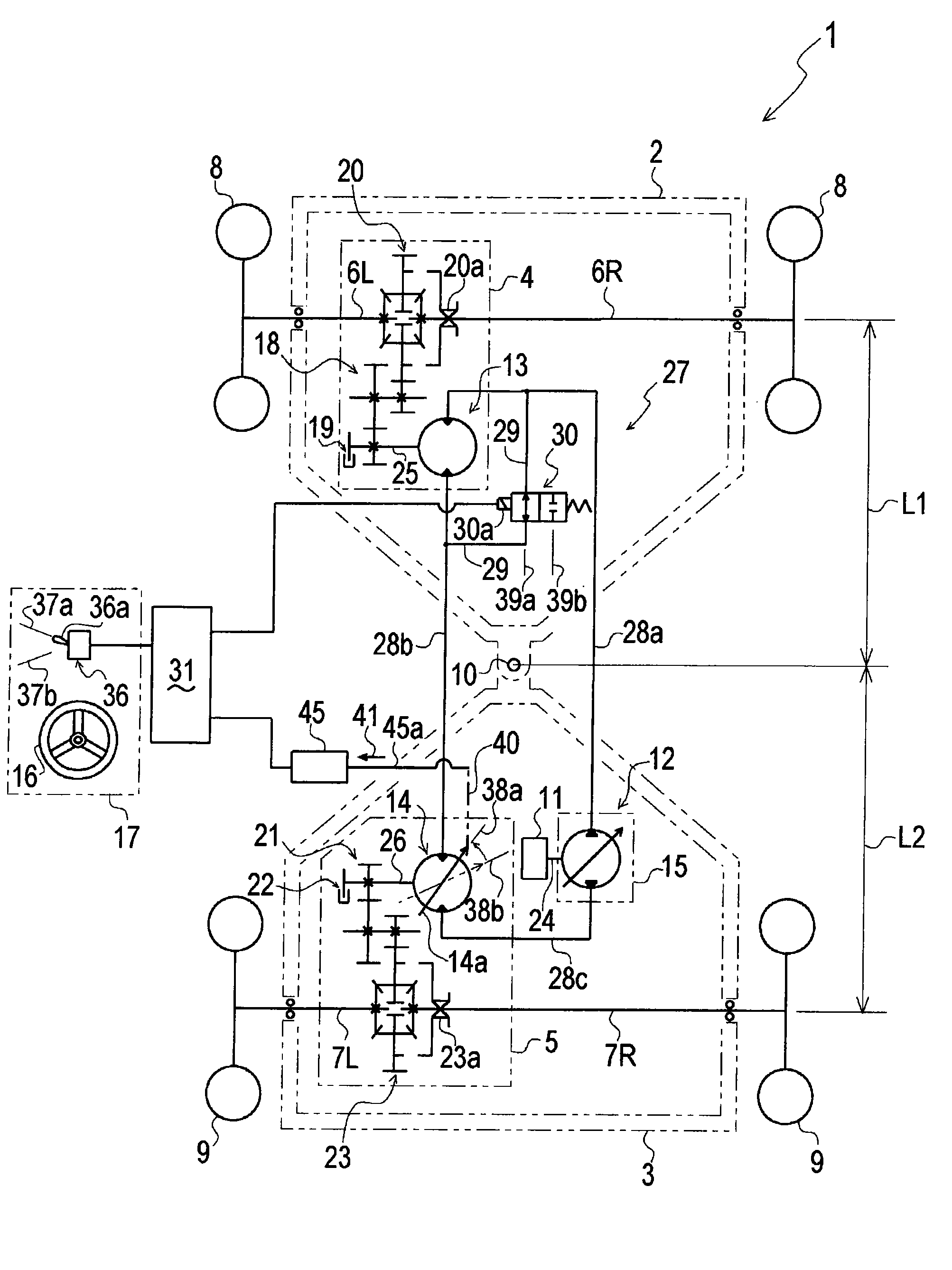
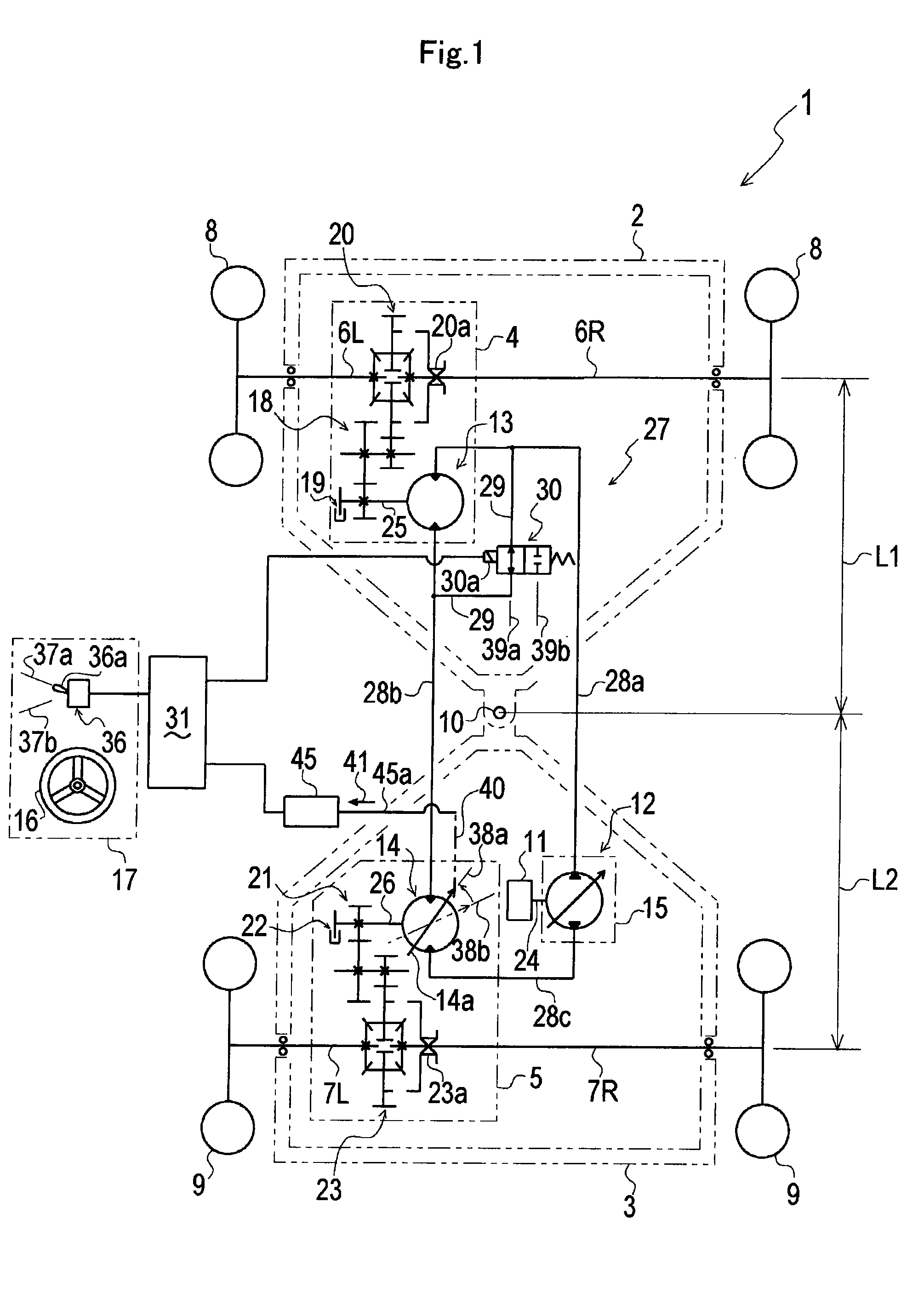
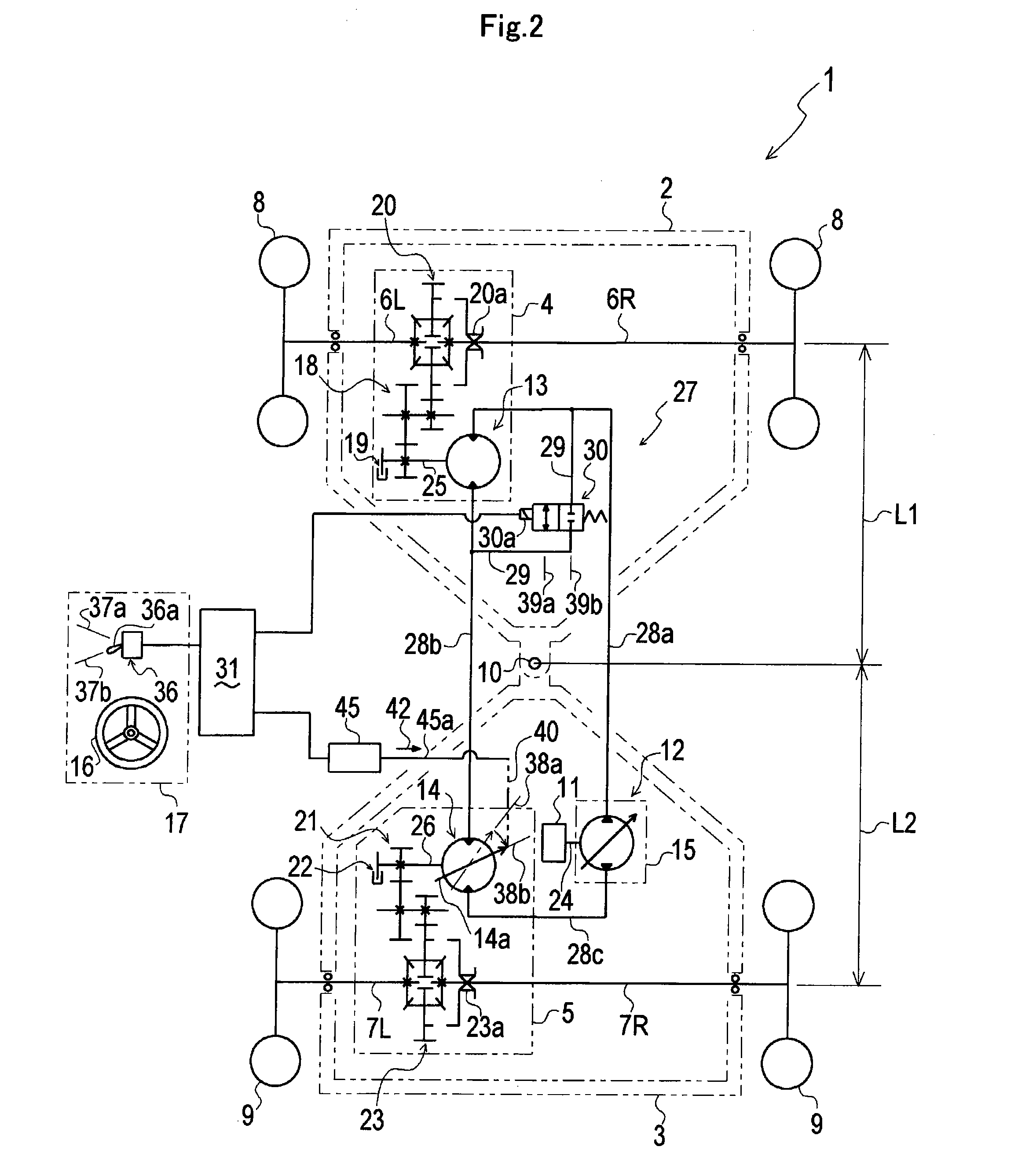
[0116]FIG. 1 and FIG. 2 illustrate schematic views of a power transmission in a four-wheel hydraulic drive vehicle 1 according to the present embodiment. Further, FIG. 1 and FIG. 2 illustrate the power transmission conditions at states where a first-motor driving mode and a first / second-motor driving mode, which will be described later, are being selected, respectively.

[0117]At first, with reference to FIG. 1 and FIG. 2, there will be described an entire structure of the hydraulic drive vehicle 1 according to the present embodiment.

[0118]As illustrated in FIG. 1 and FIG. 2, the vehicle 1 includes a vehicle frame, a pair of left and right first wheels 9 (rear wheels in the present embodiment) and a pair of left and right second wheels 8 (front wheels in the present embodiment) which are respectively supported at one side and the ...

second embodiment

[0180]Hereinafter, there will be described another embodiment of the hydraulic drive vehicle according to the present invention, with reference to the attached drawings.

[0181]FIG. 4 illustrates a schematic view of the power transmission at a state where a four-wheel hydraulic drive vehicle 1A according to the present embodiment travels straight, in the first-motor driving mode.

[0182]Further, FIG. 5 and FIG. 6 illustrate schematic views of the power transmission at a state where the vehicle 1A travels straight or makes a turn, respectively, in the first / second-motor driving mode.

[0183]In the figures, the same components as those in the first embodiment will be designated by the same reference characters, and detailed description thereof will be properly omitted.

[0184]The vehicle 1A according to the first embodiment is configured so that the distance L2 in the vehicle lengthwise direction between the pivot shaft 10 and the first wheels 9L and 9R is made equal to the distance L1 in the...

third embodiment

[0216]Hereinafter, there will be described still another embodiment of the hydraulic drive vehicle according to the present invention, with reference to the attached drawings.

[0217]FIG. 8 illustrates a partial schematic view of the power transmission in a vehicle 1B according to the present embodiment.

[0218]In the drawing, the same components as those in the first and second embodiments will be designated by the same reference characters, and detailed description thereof will be properly omitted.

[0219]As illustrated in FIG. 8, the vehicle 1B according to the present embodiment includes a second axle-driving device 4A instead of the second axle-driving device 4 in comparison with the vehicle 1 or 1A according to the first or second embodiment.

[0220]The second axle-driving device 4 in the first and second embodiments is structured to drive the pair of second wheels 8 by the single second hydraulic motor 13, as described above.

[0221]Namely, the second axle-driving device 4 includes the...


PUM


Abstract

A hydraulic drive vehicle includes a bypass valve for fluidly connecting or disconnecting a pump/second-motor line and a second-motor/first-motor line, and set a capacity of a first hydraulic motor to a standard capacity which makes a peripheral speed of a first wheel driven by the first hydraulic motor equal to a peripheral speed of a second wheel driven by a second hydraulic motor when the bypass valve fluidly disconnects the two lines and set the capacity of the first hydraulic motor to a first capacity smaller than the standard capacity when the bypass valve fluidly connects the two lines. The present invention makes it possible to widen a variable range in which a traveling speed of the vehicle could be changed.

Description

BACKGROUND OF THE INVENTION[0001]1. Field of the Invention[0002]The present invention relates to a hydraulic drive working vehicle including a variable-displacement type hydraulic pump that is operatively driven by a driving power source, and first and second hydraulic motors that respectively drive first and second wheel positioned on one and the other side in a vehicle lengthwise direction, wherein the hydraulic pump and first and second hydraulic motors are fluidly connected in series one another.[0003]2. Background Art[0004]A hydraulic drive working vehicle in which first and second wheels placed at one side and the other side in a vehicle lengthwise direction are respectively driven by first and second hydraulic motors which are fluidly connected in series to a variable-displacement type hydraulic pump has been widely used in a mowing machine and the like (refer to, for example, U.S. Pat. No. 6,889,793, which will be referred to as a prior art document 1, hereinafter).[0005]Mor...

Claims


Application Information

Patent Timeline
IPC IPC(8): B60K8/00F16H61/4043F16H61/421F16H61/431F16H61/444
CPCB60K17/105B60K17/356F16H61/4043B60Y2200/223F16H61/431F16H61/444F16H61/421
Inventor NOZAKI, TAKEAKIKAWAMURA, MASAHISAYASUDA, TOSHIFUMI
Owner KANZAKI KOKYUKOKI MFG
Why Eureka
Try Eureka