Home Node B System Architecture with Support for RANAP User Adaptation Protocol

a home node and user adaptation technology, applied in the field of telecommunication, can solve the problems of limiting the data transfer rate and range, affecting the speed and quality of service, and the frequency and frequency of typical licensed wireless systems, so as to reduce the deployment cost of the hnb-an, speed and quality of service, and reduce the deployment cost

Inactive Publication Date: 2009-10-22
KINETO WIRELESS
View PDF102 Cites 196 Cited by
  • Summary
  • Abstract
  • Description
  • Claims
  • Application Information

AI Technical Summary

Benefits of technology

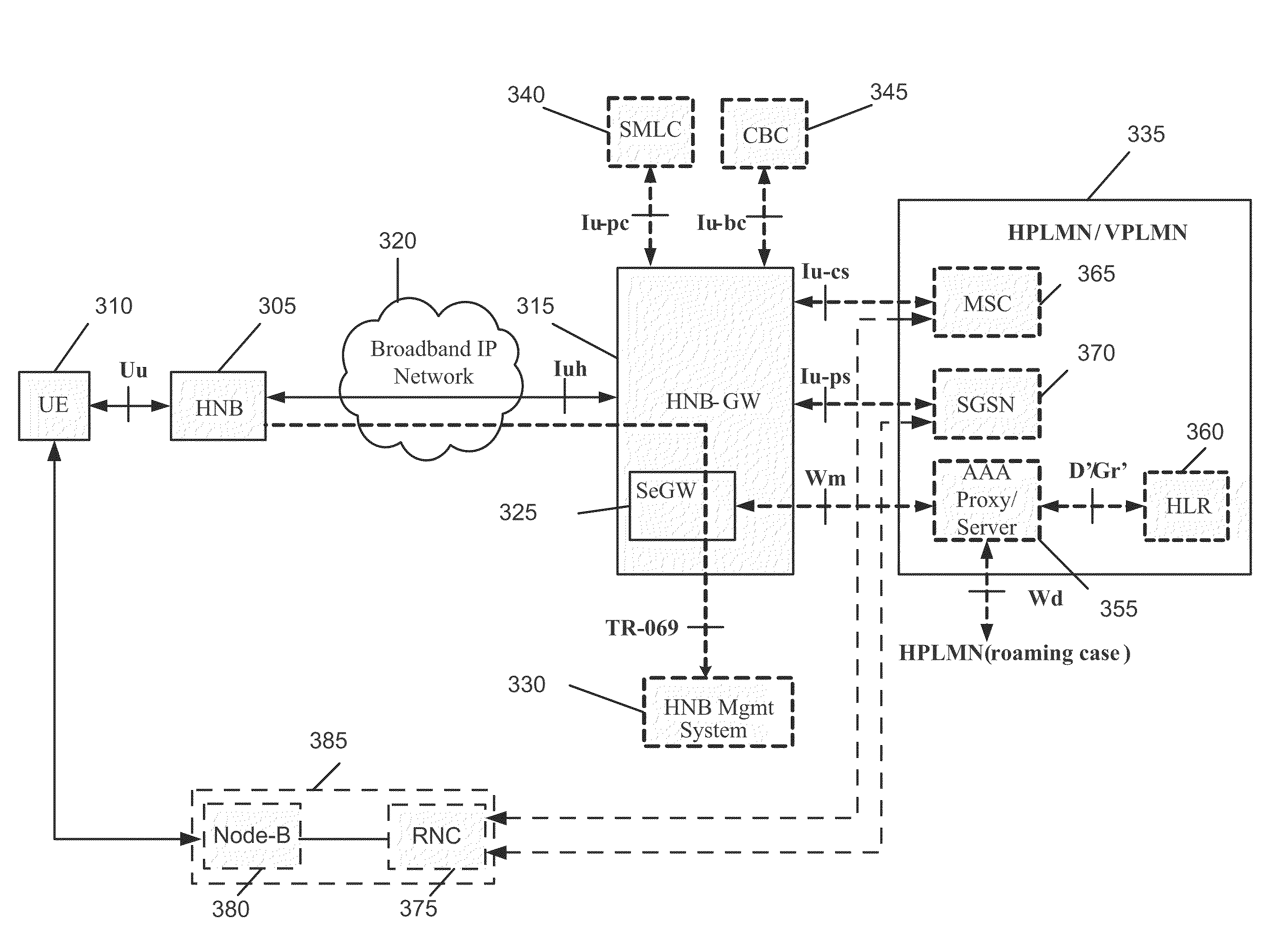
[0013]The network controller of some embodiments seamlessly integrates each of the short range licensed wireless service regions with the core network. In some such embodiments, the network controller seamlessly integrates with the core network by using existing Iu interfaces of the core network to communicatively couple each of the service regions to the core network. Accordingly, the network controller of some embodiments uses standardized messaging and protocols to communicate with the core network while utilizing HNB-AN messaging and protocols to communicate with each of the service regions. In this manner, the network controller of some embodiments reduces deployment costs of the HNB-AN within the UMTS core network. Specifically, deployment of the network controller of some embodiments requires no change to the UMTS core network while still providing HNB wireless service that combines the mobility of licensed wireless networks with the quality and speed of landline/broadband services. In some embodiments, the network controllers take on s

Problems solved by technology

The wireless transport mechanisms and frequencies employed by typical licensed wireless systems limit both data transfer rates and range.
However, with each upgrade iteration (e.g., 3 G to 4 G), the licensed wireless system providers incur substantial costs from licensing additional bandwidth spectrum to upgrading the existing radio network equipment or core network equipment.
Use

Method used


Image

  • Home Node B System Architecture with Support for RANAP User Adaptation Protocol
  • Home Node B System Architecture with Support for RANAP User Adaptation Protocol
  • Home Node B System Architecture with Support for RANAP User Adaptation Protocol

Examples


case examples

[0520]B. Service Access Control Use Case Examples

[0521]The following example service access control use cases are described in this section: (1) New HNB connects to the HNB-GW; (2) the HNB connects to the HNB-GW network (redirected connection); (3) the HNB attempts to connect in a restricted UMTS coverage area; (4) Authorized UE roves into an authorized HNB for HNB service; and (5) Unauthorized UE roves into an authorized HNB for HNB service.

[0522]1. New HNB Connects to the HNB-GW

[0523]FIG. 60 illustrates the SAC for a new HNB connecting to the HNB network, in some embodiments. This figure includes HNB 6005, public DNS 6010, SeGW #1 (provisioning SeGW) 6015, private DNS 6020, (provisioning) HNB-GW #16025, and (default / serving) HNB-GW #26030.

[0524]As shown, if the HNB 6005 has a provisioned FQDN of the Provisioning SeGW 6015, it performs (at step 1) a DNS query (via the generic IP access network interface) to resolve the FQDN to an IP address. If the HNB 6005 has a provisioned IP add...


PUM


Abstract

Some embodiments are implemented in a communication system that includes a first communication system comprised of a licensed wireless radio access network and a core network, and a second communication system comprising a plurality of user hosted access points and a network controller. In some embodiments, each access point operates using short range licensed wireless frequencies to establish a service region. In some embodiments, the network controller communicatively couples the core network to the plurality of access points. The method uses three sets of protocol layers: a security layer, a transport layer, and a layer for transferring Radio Access Network Application Part (RANAP) messages, to communicate between the network controller and one of the access points. The method also uses the Iuh interface for the transport of messages across the three sets of protocol layers.

Description

CLAIM OF BENEFIT TO RELATED APPLICATIONS[0001]This application claims the benefit of U.S. Provisional Application 61 / 046,401, entitled “Mechanisms to Relay or Transfer RANAP Messages between 3 G Home Node-B and the Core Network via the Home Node-B Gateway”, filed Apr. 18, 2008; U.S. Provisional Application 61 / 055,961, entitled “Mechanisms to Transport RANAP Messages between 3 G Home Node-B and the Core Network via the Home Node-B Gateway”, filed May 23, 2008; U.S. Provisional Application 61 / 058,912, entitled “Transport of RANAP Messages over the Iuh Interface”, filed Jun. 4, 2008; U.S. Provisional Application 61 / 080,227, entitled “HNB System Architecture”, filed Jul. 11, 2008; and U.S. Provisional Application 61 / 101,148, entitled, “Support for Closer Subscriber Group (CSG) in Femtocell System”, filed Sep. 29, 2008. The contents of Provisional Applications 61 / 046,401, 61 / 055,961, 61 / 058,912, 61 / 080,227, and 61 / 101,148 are hereby incorporated by reference.FIELD OF THE INVENTION[0002]T...

Claims


Application Information

Patent Timeline
IPC IPC(8): H04L29/06
CPCH04L63/104H04L2012/5607H04L2012/5656H04W8/16H04W12/08H04W36/0055H04W36/14H04W48/18H04W60/04H04W84/045H04W92/12H04W36/0066H04W76/32H04W76/12H04W12/73H04W12/72H04L51/222
Inventor KHETAWAT, AMITTAO, PATRICKGALLAGHER, MICHAEL D.GUPTA, RAJEEV
Owner KINETO WIRELESS
Why Eureka
Try Eureka