
Log cartridge burning system

a burning system and log cartridge technology, applied in the direction of combustion types, household stoves or ranges, combustion types, etc., can solve the problems of inability to use artificial fuels and fire starters for cooking, fuel density is so high, and the fuel is difficult to start, so as to achieve the effect of convenient utilization

Inactive Publication Date: 2009-10-29
LEE HENRY K
View PDF11 Cites 10 Cited by
  • Summary
  • Abstract
  • Description
  • Claims
  • Application Information

AI Technical Summary

Benefits of technology

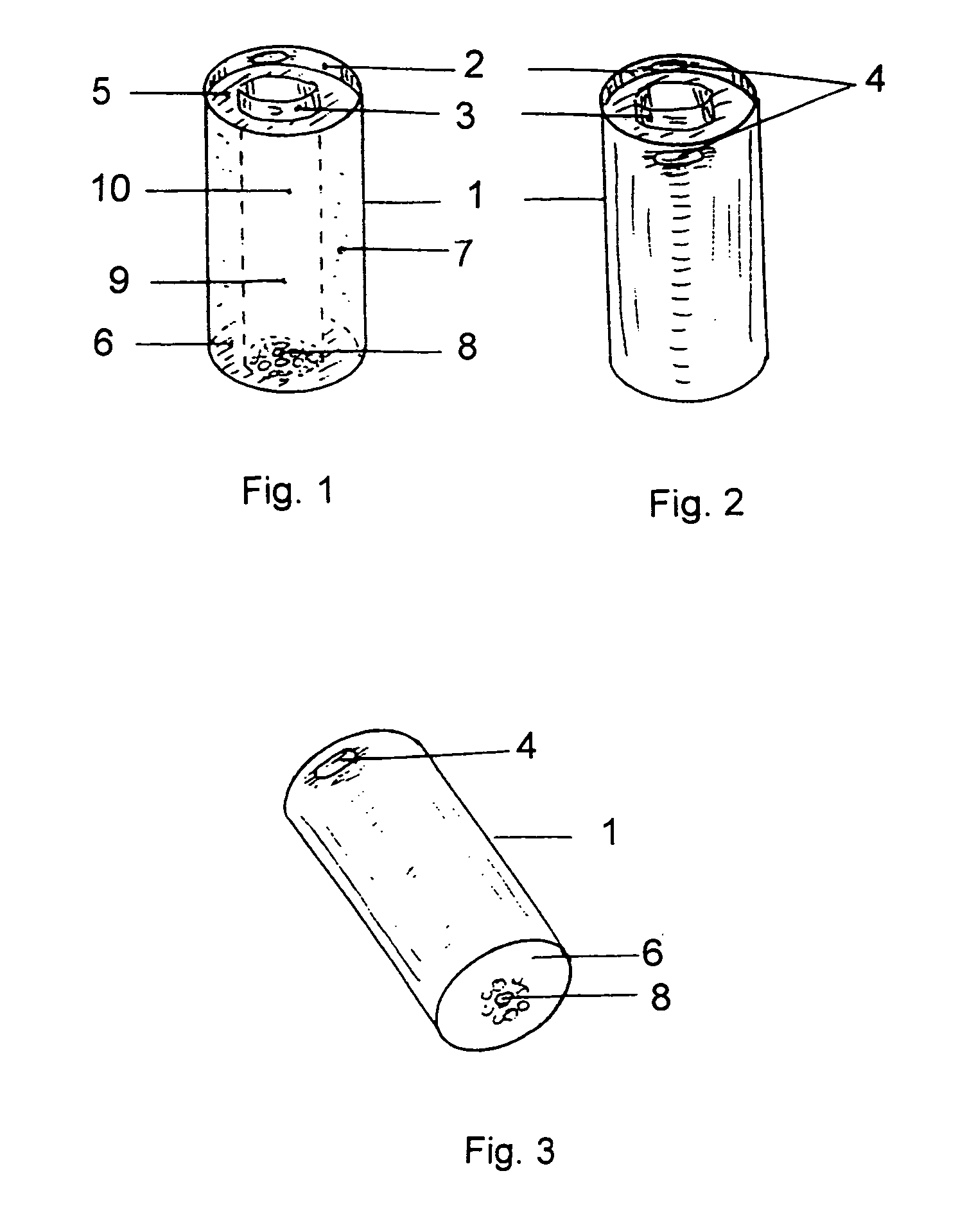
[0025]The Log Cartridge Burning System is a simple, convenient and manageable wood burning system which can easily be applied for use to cook and heat. The log cartridge is comprised of a flammable body of compressed material such as sawdust formed and sealed by the use of a protective outer paperboard tube and a protective inner paperboard tube together with a top and bottom paperboard cover which serve to hold and maintain the integrity of the entire cartridge without the use of any wax binders.
[0026]The paperboard tubes and top and bottom covers also prevent the damaging and breaking up of the compressed fuel body during handling or shipping and the flying out or falling off of sawdust from the log cartridge. In addition, the paperboard covers also form part of the fuel body and provide a clean, tidy and neat packaging for easy handling and storing.
[0027]It is an object of the present invention to provide a log cartridge and burn pot which provides a simple, fast and convenient wood burning technology for use to cook and heat.
[0031]It is a further object of the present invention to provide a log cartridge burning system which can easily be utilized in a variety of appliances such as a patio heater or fireplace, barbecue or grill, or other cooking or heating appliances.

Problems solved by technology

These artificial fuels and fire starters cannot be used for cooking.
In fact, these fuels are so dense and they are more difficult to start compared to cordwood and they are generally used in a home fireplace or a complicated pellet stove to burn effectively.

Method used


Image

  • Log cartridge burning system
  • Log cartridge burning system
  • Log cartridge burning system

Examples


Embodiment Construction

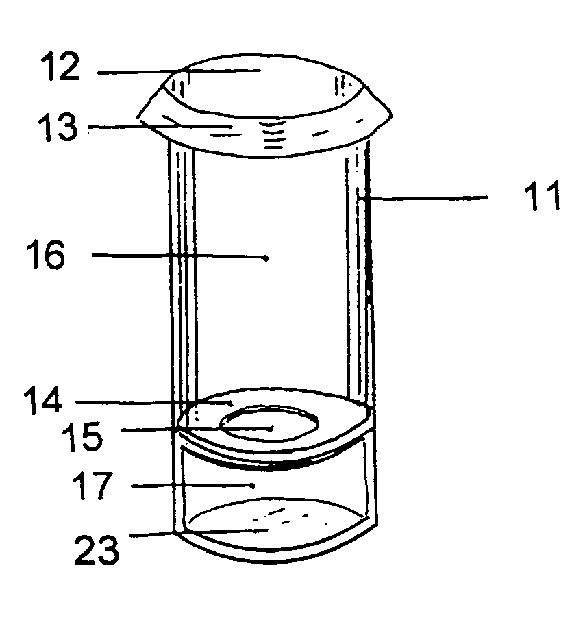
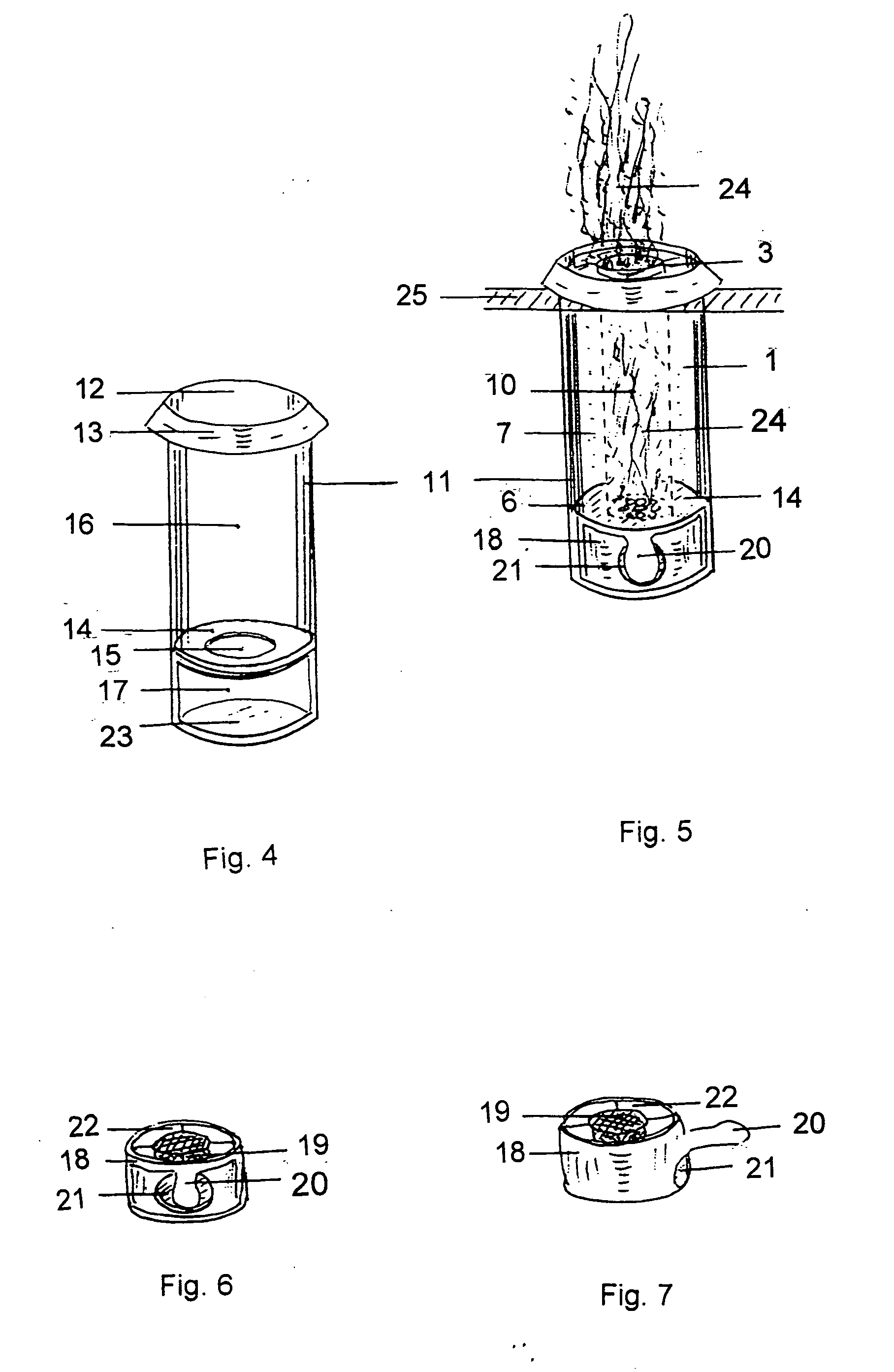
[0045]To facilitate understanding the present invention, following is a list of drawing elements and their respective numerals.[0046](1) Log Cartridge[0047](2) Protective Outer Paper Tube[0048](3) Protective Inner Paper Tube; where the diameter of the inner paper tube is smaller than the diameter of the outer paper tube and the inner paper tube is positioned inside the outer paper tube[0049](4) Grab Holes[0050](5) Top Paperboard Cover[0051](6) Bottom Paperboard Cover[0052](7) Compressed flammable material, such as sawdust, which is positioned between the protective outer paper tube and the protective inner paper tube[0053](8) Ventilation Holes[0054](9) Internal combustion chamber[0055](10) Cylindrical central bore formed by the protective inner paper tube[0056](11) Burn Pot[0057](12) Top Loading Open End[0058](13) Broad Rim Mounting Head[0059](14) Log Cartridge Receiving Plate[0060](15) Air Intake[0061](16) Combustion Chamber[0062](17) Air Chamber[0063](18) Removable Ash Bucket[0064...


PUM


Abstract

A Log Cartridge Burning System is provided comprising a simple, convenient and manageable wood burning system which can easily be applied for use to cook and heat. The log cartridge is comprised of a flammable body of compressed material and a bore formed and sealed by the use of a protective outer paperboard tube and a protective inner paperboard tube together with a top and bottom paperboard cover which serve to hold and maintain the integrity of the entire cartridge without the use of any wax binders. The flammable body of compressed material may be made partly or entirely from natural combustible materials such as sawdust or wheat hulls. The burn pot is specially designed to accommodate the log cartridge of the present invention. The log cartridge burning system can easily be utilized in a variety of appliances such as a patio heater or fireplace, barbecue or grill, or other cooking and heating appliances.

Description

CLAIM OF PRIORITY [0001]This patent application claims priority under 35 USC 119 (e) (1) from U.S. Provisional Patent Application Ser. No. 61 / 125,824, filed Apr. 29, 2008, of common inventorship herewith entitled, “Log Cartridge and Burn Pot.”FIELD OF THE INVENTION [0002]This invention pertains to the field of compressed fuel and compressed fuel combustion chambers.BACKGROUND OF THE INVENTION [0003]The prior art has put forth a variety of compressed fuel devices, methods and apparata. For example, U.S. Pat. No. 4,414,906 to Hartouni described a Fuel Cartridge and Burner wherein the cartridge is completely enclosed in the combustion chamber.[0004]Another example is found in U.S. Pat. No. 4,243,393 to Christian which describes a coal article comprising coal particles and igniter material having a hollow core to facilitate the combustion of the fuel.[0005]Further examples include:[0006]U.S. Pat. No. 2,222,250, “Fuel Briquette” to Bowling describes a log comprised of biomass having a re...

Claims


Application Information

Patent Timeline
IPC IPC(8): F24B13/02C10L11/00
CPCF23Q13/04F24B1/00Y02E50/30F24B3/00Y02E50/10F24B1/202Y02A40/928
Inventor LEE, HENRY K.
Owner LEE HENRY K
Learn More