
Method of flatting evaporating section of heat pipe embedded in heat dissipation device and heat dissipation device with heat pipe

a technology of heat dissipation device and heat pipe, which is applied in the direction of electrical apparatus construction details, indirect heat exchangers, lighting and heating apparatus, etc., can solve the problems of inability of heat dissipation devices to efficiently remove heat from electronic devices, increase in heat generation of electronic devices, and ineffective use of heat conductivity of heat pipes. , to achieve the effect of reducing the importance of the base in heat conductivity, effective heat conductivity of heat pipes, and reducing the importance of heat conductivity material

Inactive Publication Date: 2009-10-29
GOLDEN SUN NEWS TECHN +1
View PDF8 Cites 22 Cited by
  • Summary
  • Abstract
  • Description
  • Claims
  • Application Information

AI Technical Summary

Benefits of technology

[0009]The present invention provides a method of flatting an evaporating section of a heat pipe embedded in a heat dissipation device and the heat dissipation device with heat pipe. The method makes the evaporating section of the heat pipe protruding out of a base of the heat dissipation device. Such that, when the heat dissipation device contacts with an electronic device, the evaporating section of the heat pipe can function as a direct thermal contacting portion. Thus, high heat conductivity of the heat pipe is effectively utilized. Accordingly, the importance of the base in heat conductive is reduced. As a result, it is not necessary to make the base using high heat conductivity material. The cost of the heat dissipation device is therefore decreased.

Problems solved by technology

During operation of an electronic device, a large amount of heat is always produced.
However, since the electronics technology continues to advance, amount of the heat generated by the electronic devices increases enormously.
Many conventional heat dissipation devices are no longer able to efficiently remove heat from these electronic devices.
However, as the heat pipe is embedded in the base, it is difficult to make the evaporating section of the heat pipe so flatted to be coplanar with the bottom surface of the base of the heat dissipation device.
As a result, when the heat dissipation device is used in the electronic device, it is difficult to make sure which one of the evaporating section of the heat pipe and the base of the heat dissipation device thermally contacts with the electronic device.

Method used


Image

  • Method of flatting evaporating section of heat pipe embedded in heat dissipation device and heat dissipation device with heat pipe
  • Method of flatting evaporating section of heat pipe embedded in heat dissipation device and heat dissipation device with heat pipe
  • Method of flatting evaporating section of heat pipe embedded in heat dissipation device and heat dissipation device with heat pipe

Examples


Embodiment Construction

[0023]These and other features and advantages of the various embodiments disclosed herein will be better understood with respect to the following description and drawings, in which like numbers refer to like parts throughout, and in which:

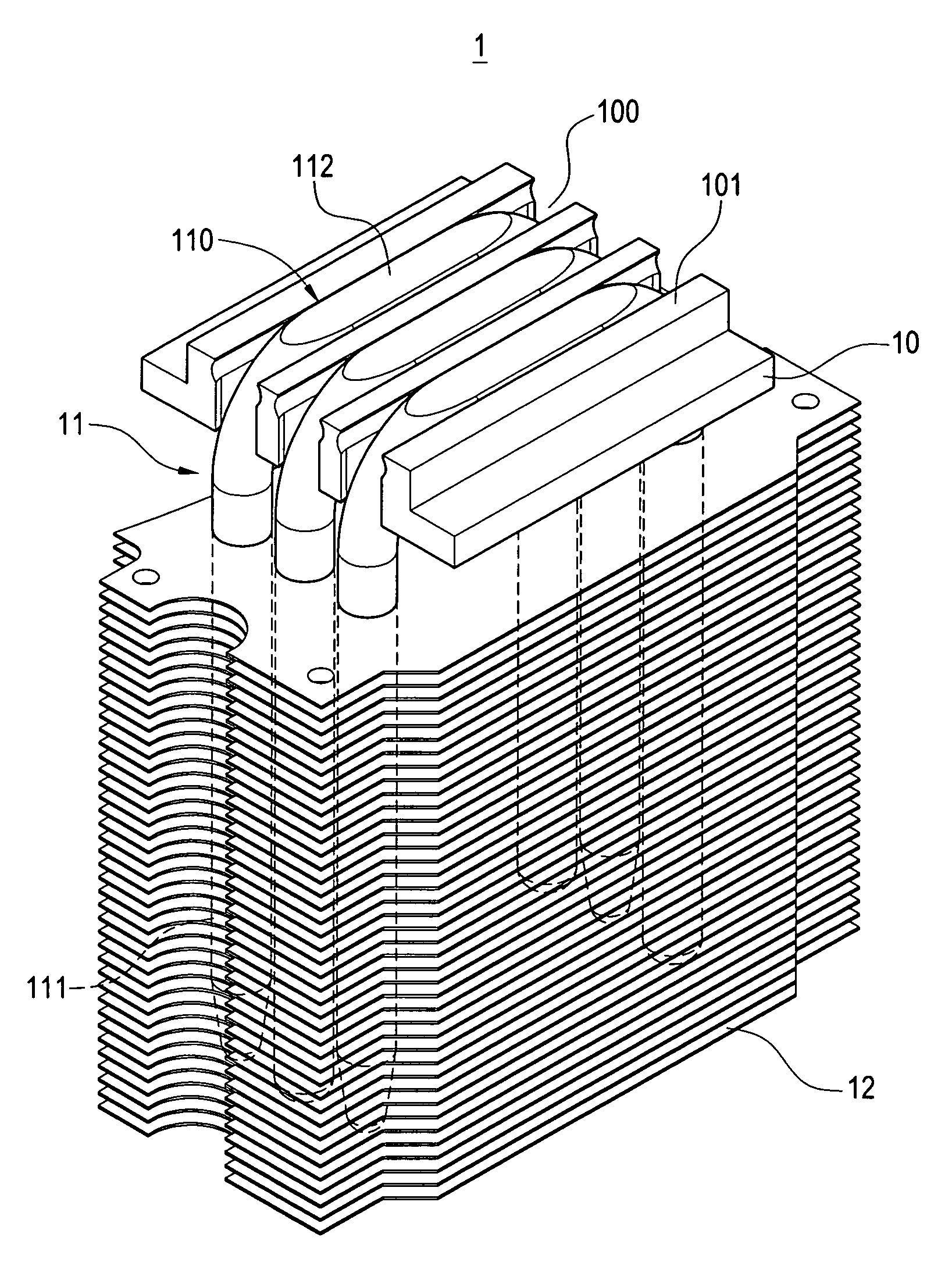
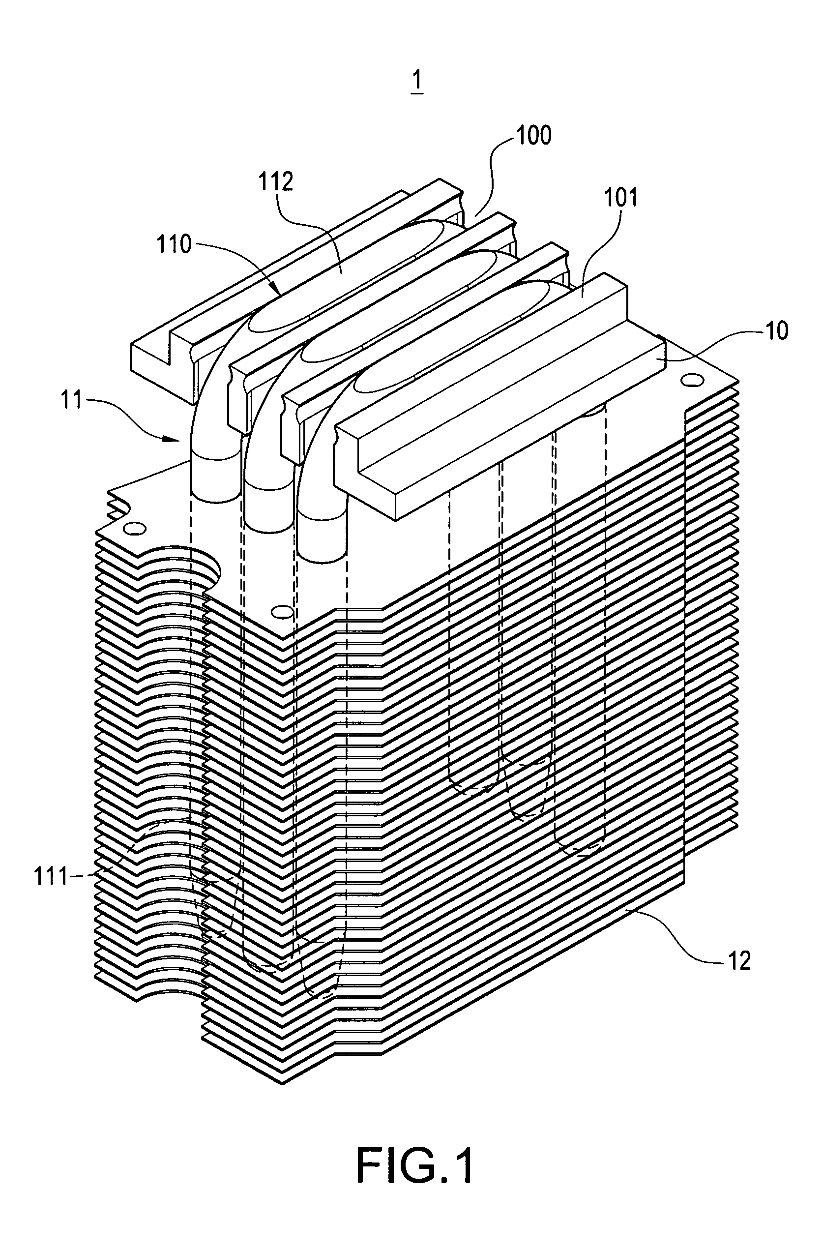
[0024]Referring to FIG. 1, a schematic isometric view of a heat dissipation device with heat pipe in accordance with an exemplary embodiment is shown. The heat dissipation device 1 includes a base 10, at least one heat pipe 11, and a number of fins 12.

[0025]The base 10 defines at least one groove 100 in a bottom surface 101 thereof for the heat pipe 11 being embedded therein.

[0026]Each heat pipe 11 includes a heat evaporating section 110 and a condensing section 111. In this embodiment of the present invention, each heat pipe 11 has a U-shaped structure. Such that the heat evaporating section 110 is positioned at the middle portion of the U-shaped heat pipe 11 and the condensing section 111 is positioned at each of two ends of the U-shaped heat pip...


PUM

PropertyMeasurementUnit
heat conductiveaaaaaaaaaa
heataaaaaaaaaa
phaseaaaaaaaaaa

Abstract

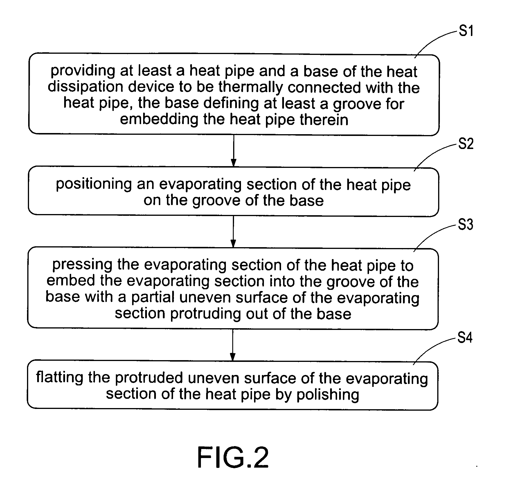
A method of flatting evaporating section of a heat pipe embedded in a heat dissipation device includes the following steps: (a) providing at least a heat pipe and a base of the heat dissipation device to be thermally connected with the heat pipe, the base defining at least a groove for embedding the heat pipe therein; (b) positioning an evaporating section of the heat pipe on the groove of the base; (c) pressing the evaporating section of the heat pipe to embed the evaporating section into the groove of the base with a partial uneven surface of the evaporating section protruding out of the base; (d) flatting the protruded uneven surface of the evaporating section by polishing.

Description

BACKGROUND[0001]1. Technical Field[0002]The present invention is related to a method of manufacture heat dissipation device, and particularly to a heat dissipation device with heat pipe and a method of flatting an evaporating section of the heat pipe thereof.[0003]2. Description of the Related Art[0004]During operation of an electronic device, a large amount of heat is always produced. The heat must be quickly removed from the electronic device to prevent it from becoming unstable or being damaged. Typically, a heat dissipation device is attached to an outer surface of the electronic device to absorb heat from the electronic device. The heat absorbed by the heat dissipation device is then dissipated to ambient air.[0005]Conventionally, a heat dissipation device comprises a solid metal base attached on the electronic device, and a plurality of fins arranged on the base. The base is intimately attached on the electronic device thereby absorbing the heat generated by the electronic dev...

Claims


Application Information

Patent Timeline
Patent Type & Authority Applications(United States)
IPC IPC(8): F28D15/02B21D53/02
CPCB21D53/02F28D15/0233F28F2275/12H01L21/4882H01L23/427Y10T29/49353F28F2013/006H01L2924/0002F28D15/0275H01L2924/00
Inventor LIN, KUO-LENLIU, WEN-JUNGCHENG, CHIH-HUNGHSU, KEN
Owner GOLDEN SUN NEWS TECHN
Learn More