Portable wireless apparatus

a wireless apparatus and portable technology, applied in the direction of electrical apparatus, antenna details, antennas, etc., can solve the problems of deterioration of the antenna performance, physical difficulty in maintaining the distance between the antennas, etc., to achieve high diversity gain, high transmission speed, and relieve the effect of efficiency deterioration

Inactive Publication Date: 2009-10-29
PANASONIC CORP
View PDF7 Cites 19 Cited by
  • Summary
  • Abstract
  • Description
  • Claims
  • Application Information

AI Technical Summary

Benefits of technology

[0024]According to the invention, it is possible to provide a portable wireless apparatus capable of relieving a deterioration in an efficiency which is caused by coupling between antennas and obtaining a high diversity gain, and a high transmission speed and a large communication capacity in an MIMO system.

Problems solved by technology

For this reason, it is physically hard to maintain the distance between the antennas.
If the distance between the antennas is short, thus, there is a problem in that the antennas are electromagnetically coupled to each other, resulting in deterioration in an antenna performance.
On the other hand, in the same manner as in the case in which the diversity antenna is used, it is physically hard to maintain a distance between the antennas because a housing has a small size in the case of a portable telephone.
In the case in which the distance between the antennas is short, thus, there is a problem in that the antennas are electromagnetically coupled to each other, resulting in deterioration in an antenna performance.

Method used


Image

  • Portable wireless apparatus
  • Portable wireless apparatus
  • Portable wireless apparatus

Examples


first embodiment

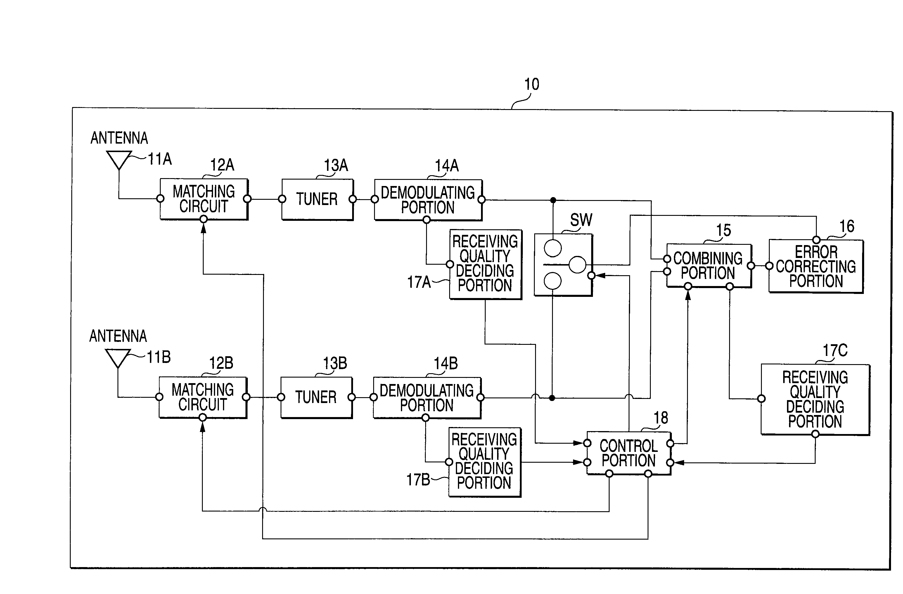
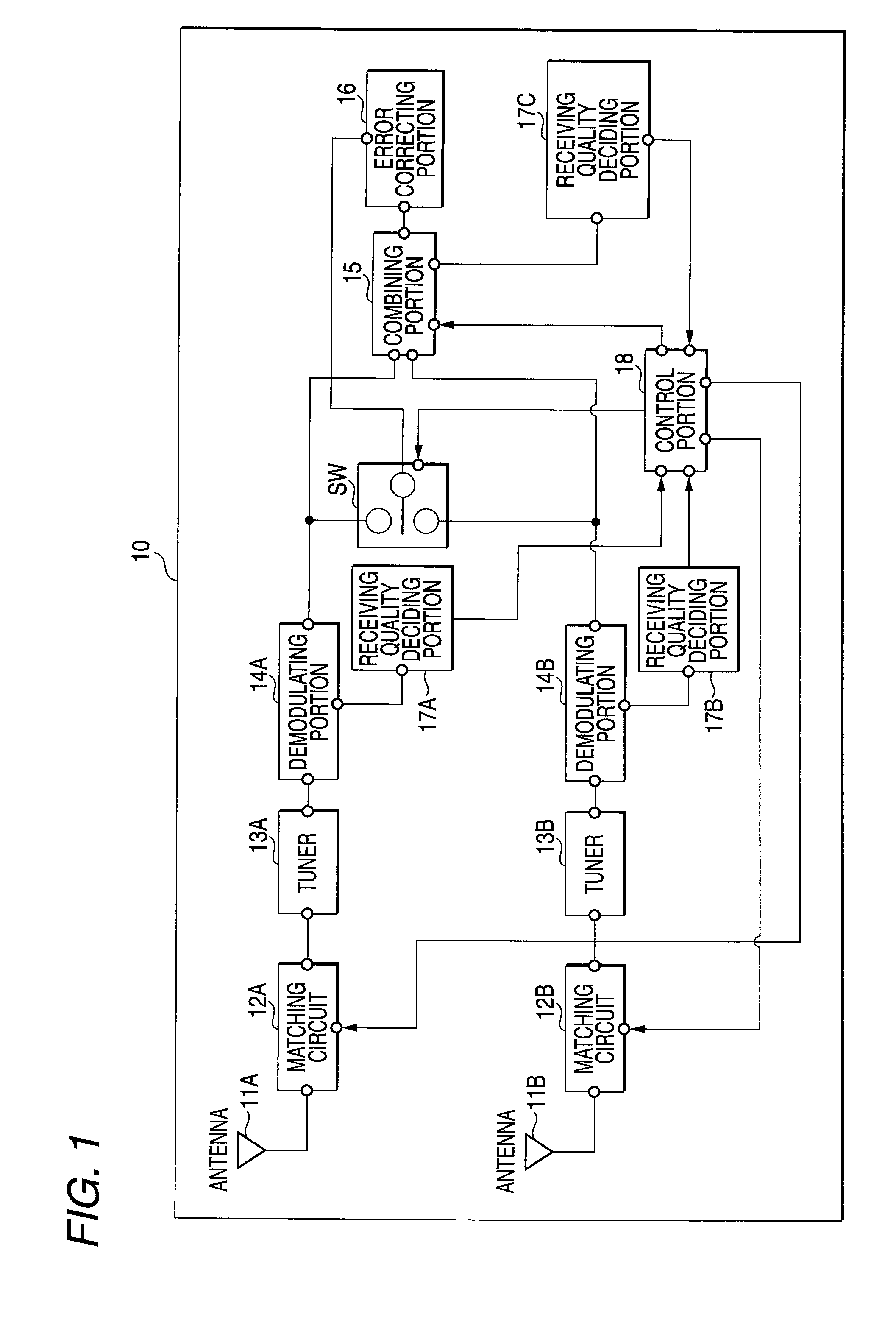
[0055]FIG. 1 shows a portable wireless machine to be one of portable wireless apparatuses according to a first embodiment of the invention.

[0056]A portable wireless machine 10 according to the embodiment is constituted by a plurality of antennas 11A and 11B for receiving a digital modulating signal, a matching circuit 12A and a matching circuit 12B which are individually set to two types of antennas 11A and 11B respectively, a plurality of tuners 13A and 13B for selecting a desirable channel in response to an input digital signal, a plurality of demodulating portions 14A and 14B for demodulating the selected signal, a combining portion 15 constituting a combined diversity processing portion for combining a received and demodulated signal through each receiving system, an error correcting portion 16 for carrying out an error correction processing, receiving quality deciding portions 17A, 17B and 17C for calculating a numeric value (which will be hereinafter referred to as a “receivin...

second embodiment

[0091]Next, description will be given to a portable wireless machine according to a second embodiment of the invention. In the embodiment, the same portions as those in the first embodiment have the same reference numerals and repetitive description will be omitted.

[0092]First of all, a basic structure of the portable wireless machine according to the embodiment will be described with reference to FIG. 10.

[0093]As shown in FIG. 10, a portable wireless machine 20 comprises two antennas 11A and 11B, two tuners 13A and 13B, two demodulating portions 14A and 14B, a combining portion 15, an error correcting portion 16, receiving quality deciding portions 17A, 17B and 17C, a control portion 18 for carrying out a control in a receiving mode, and a switch SW for switching each of a single branch receipt and a combined diversity receipt which are the same as those in the first embodiment, and furthermore, a matching circuit 21A and a matching circuit 21C which serve to apply matching conditi...

third embodiment

[0120]Next, a portable wireless machine according to a third embodiment of the invention will be described with reference to FIG. 12.

[0121]First of all, a basic structure of a portable wireless machine 30 according to the embodiment will be described. The invention can apply to a portable wireless machine of an MIMO system having a plurality of antennas and a receiving structure of the MIMO system having four receiving antennas will be described in the embodiment. In the embodiment, moreover, the same portions as those in the first and second embodiments have the same reference numerals and repetitive description will be omitted.

[0122]As shown in FIG. 12, the portable telephone 30 according to the embodiment comprises four types of antennas 11A to 11D, four matching circuits 12A to 12D provided corresponding to the four types of antennas respectively and serving to set matching conditions capable of maintaining the highest antenna performances to the respective antennas, a receiving...


PUM


Abstract

It is an object to relieve deterioration in efficiency due to the influence electromagnetic coupling between antennas and to obtain a high diversity gain, and a high transmission speed and a large communication capacity in an MIMO system. In a portable wireless machine including two types of antennas 11A and 11B for receiving a digital modulating signal, matching circuits 12A and 12B set individually to the antennas 11A and 11B respectively, tuners 13A and 13B, demodulating portions 14A and 14B, a combining portion 15 for combining a demodulated signal, and receiving quality deciding portions 17A, 17B and 17C for outputting receiving qualities in respective branches and after a combination, a diversity effect decision is made by using the receiving quality after the combination and a receiving quality in a single branch receipt, and a matching condition of the matching circuit 12A or the matching circuit 12B of the antenna 11A or the antenna 11B is controlled corresponding to a result.

Description

TECHNICAL FIELD[0001]The present invention relates to a portable wireless apparatus loading a diversity receiver, and a portable wireless apparatus loading a receiver of a multi input multi output system (Multiple Input Multiple Output system or an MIMO system).BACKGROUND ART[0002]A diversity antenna to be loaded onto a portable wireless apparatus, for example, a portable telephone generally has a structure in which two antennas are loaded into a housing of the portable telephone. Examples of a main diversity method include a selecting diversity system for selecting either of signals received by the respective antennas which has a higher receiving quality and a combined diversity system for simultaneously receiving and combining signals in two branches described in Patent Document 1, for example. In order to constitute a diversity antenna, generally, the antennas are disposed at a distance of approximately λ / 2 (λ; wavelength). In the case of a portable telephone, however, a housing ...

Claims


Application Information

Patent Timeline
Patent Type & Authority Applications(United States)
IPC IPC(8): H01Q1/24H01Q3/24
CPCH04B1/18H04B7/0871H04B7/0837H04B7/082
Inventor TAKAGI, KENJIHAYASHI, TOSHITERUTAKAHASHI, TSUKASASAITO, YUTAKA
Owner PANASONIC CORP
Why Eureka
Try Eureka