Hydrostatic Pump With A Mechanical Displacement Volume Control

Active Publication Date: 2009-10-29
LINDE HYDRAULICS
View PDF6 Cites 2 Cited by
  • Summary
  • Abstract
  • Description
  • Claims
  • Application Information

AI Technical Summary

Benefits of technology

[0011]The invention teaches that the control lever is mechanically uncoupled from the displacement setting device, whereby a pressure cutoff function is provided in which, by means of respective pilot valves, a pressure signal can be generated from a delivery line of the pump. The pressure signal is transmitted via the control valve to the positioning piston and counteracts the control pressure. It has been shown that the mechanically positive coupling between the control lever and the displacement setting device, which was provided in the known art for an emergency actuation of the displacement setting device, can be eliminated because the hydraulic natural setting torque of the displacement setting device makes a mechanical positive tracking of the displacement setting device by the actuated control level superfluous. It thereby becomes possible to provide a pressure cutoff function on a pump with a mechanical displacement volume control. The invention teaches that the positive coupling of the control lever with the displacement setting device can be eliminated and a pressure cutoff function is provided in which, by means of the pilot valve, a pressure signal is generated from the delivery line which counteracts the control pressure on the positioning piston and thus reverses the positioning torque on the displacement setting device. Consequently, when the pressure cutoff function responds, the pump is controlled in the direction of a reduction of the displacement volume. The intervention signal for the pressure cutoff function is sent over the shortest possible distance by the pressure signal that acts opposite to the control pressure. As a result, interference caused by friction is eliminated and response times are minimized by a short signal path. With a pressure cutoff function of this type which counteracts the control pressure of the positioning piston generated via the control valve and reverses the positioning torque of the displacement setting device, it becomes easily possible to provide a pressure cutoff function on a pump with a mechanical displacement volume control.
[0012]In one embodiment of the invention, the control valve has a first control pressure port in communication with a first control pressure chamber of the positioning piston, a second pressure port in communication with a second control pressure chamber of the positioning piston, a supply pressure port in communication with a supply pressure source, and a first tank port in communication with a reservoir, as well as a second tank port in communication with the reservoir. In a first switching position of the control valve, the first control pressure port is in communication with the supply pressure port and the second control pressure port is in communication with the second tank port, and the first tank port is closed. In a second switching position of the control valve, the second control pressure port is in communication with the supply pressure port and the first control pressure port is in communication with the first tank port and the second tank port is closed. The tank ports are each in communication with the reservoir by individual reservoir lines, in each of which a throttle device is located, whereby the pressure signal generated by the pilot valve is transmitted to the reservoir line upstream of the throttle device. With a control valve of this type which has separate tank drains, it is easily possible to transmit the pressure signal of the pressure cutoff function to the respective tank side of the positioning piston and thus to realize a pressure cutoff function for a bilaterally controllable pump. By means of the throttle device, the pressure signal generated from the pilot signal builds up in the reservoir line and counteracts the control pressure on the positioning piston. As a result, on account of the pressure signal, the positioning torque of the displacement setting device is reversed by the pressure signal and, therefore, the pressure cutoff function can be achieved in the acceleration phase and in the braking phase with little construction expense.
[0013]When the control valve is moved in the direction of the first switching position, the pump delivers into a first delivery line. When the control valve is moved in the direction of the second switching position, the pump delivers into a second delivery line. A first branch line is provided with the first pilot valve which connects the first delivery line with the second reservoir line of the control valve upstream of the throttle device, and a second branch line is provided with the second pilot valve which connects the second delivery line with the first reservoir line of the control valve upstream of the throttle device. Thus, it is easily possible to connect the respective reservoir line and thus the tank drain of the control valve via the corresponding branch line with the delivery line, so that a pressure cutoff function can be achieved in both delivery directions of the pump, in the acceleration phase and the braking phase.

Problems solved by technology

With pressure relief valves, simply constructed pilot valves can be made available for the pressure cutoff function, as a result of which the pressure cutoff function entails a small amount of effort and expense in design and manufacture.

Method used


Image

  • Hydrostatic Pump With A Mechanical Displacement Volume Control
  • Hydrostatic Pump With A Mechanical Displacement Volume Control
  • Hydrostatic Pump With A Mechanical Displacement Volume Control

Examples


Embodiment Construction

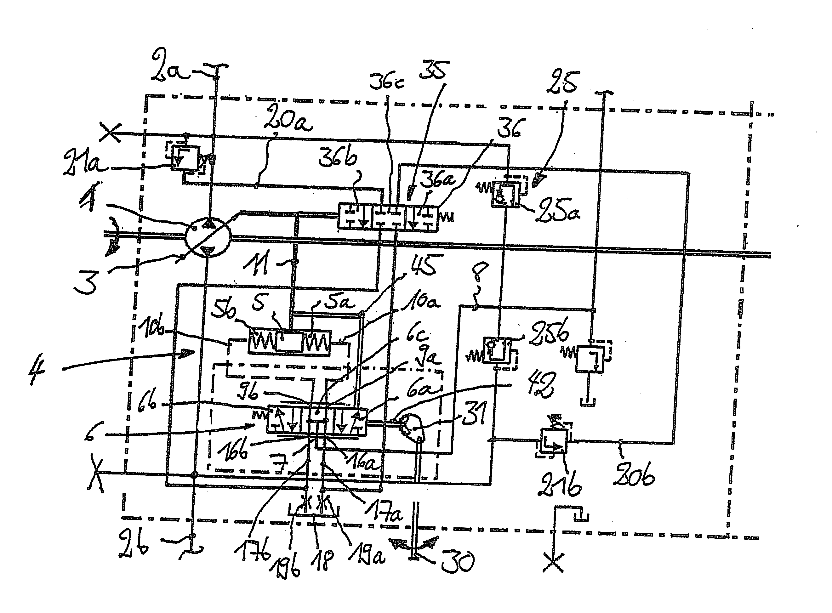
[0026]FIG. 2 shows the circuit diagram of a pump 1 of the invention which is operated in a closed circuit, for example of a traction drive of a mobile work machine.

[0027]The pump 1 is driven by a drive motor which is not illustrated in any further detail, such as an internal combustion engine or an electric motor, for example, and is in communication via a first delivery line 2a and a second delivery line 2b which form the closed circuit with a consumer which is not illustrated in any further detail.

[0028]The pump 1 is a variable displacement pump and has a displacement setting device 3, such as a swashplate, for example, which is realized in the form of a cradle, which is functionally connected with a mechanical displacement volume control in the form of a mechanical control element 4.

[0029]The control element 4 has a spring-centered positioning piston 5 which is in functional communication with the displacement setting device 3 and is provided with a first control pressure chamber...


PUM


Abstract

A hydrostatic pump (1) has a mechanical displacement volume control with a mechanical control element (4), which for generation of an actuator pressure that acts on a positioning piston (5) which is functionally connected with a displacement setting device (3), has a position-controlled control valve (6) functionally connected with a control lever (30) and with the displacement setting device (3) of the pump (1). A pump with a mechanical displacement volume control with a pressure limiting function can be accomplished by mechanically decoupling the control lever (30) from the displacement setting device (3) whereby a pressure cutoff function is provided, with which, by respective pilot valves (21a, 21b), a pressure signal can be generated from a delivery line (2a, 2b) of the pump (1), which signal is transmitted via the control valve (6) to the positioning piston (5) and counteracts the control pressure.

Description

CROSS-REFERENCE TO RELATED APPLICATION[0001]This application claims priority to German Application DE 10 2008 020 596.6, filed Apr. 24, 2008, which is herein incorporated by reference in its entirety.BACKGROUND OF THE INVENTION[0002]1. Field of the Invention[0003]This invention generally relates to a hydrostatic pump with a variable displacement volume which can be operated in a closed circuit. The pump has a mechanical displacement volume control with a mechanical control element. The mechanical control element comprises a piston-controlled control valve for the generation of a control pressure that acts on a positioning piston, which is functionally connected with a displacement volume setting device, in particular a swashplate. The position-controlled control valve is functionally connected with a control lever and with the displacement setting device of the pump.[0004]2. Technical Considerations[0005]Hydrostatic pumps of this general type with variable displacement volumes which...

Claims


Application Information

Patent Timeline
IPC IPC(8): F04B49/12
CPCF04B49/002
Inventor STEIGERWALD, MARTINSTURMER, BURKHARD
Owner LINDE HYDRAULICS
Why Eureka
Try Eureka