Coating apparatus and coating method

a coating apparatus and coating technology, applied in the direction of coatings, liquid surface applicators, chemical vapor deposition coatings, etc., can solve the problem of significant reduction in and achieve the effect of reducing the manufacturing yield of epitaxial wafers

Inactive Publication Date: 2009-10-29
NUFLARE TECH INC
View PDF5 Cites 19 Cited by
  • Summary
  • Abstract
  • Description
  • Claims
  • Application Information

AI Technical Summary

Benefits of technology

[0010]If the wafer comes out of alignment with the susceptor due to the cause described above, a coating cannot be formed on the wafer, resulting in a significant reduction in th...

Problems solved by technology

If the wafer comes out of alignment with the susceptor due to the cause described above, a coating cannot...

Method used


Image

  • Coating apparatus and coating method
  • Coating apparatus and coating method
  • Coating apparatus and coating method

Examples


Embodiment Construction

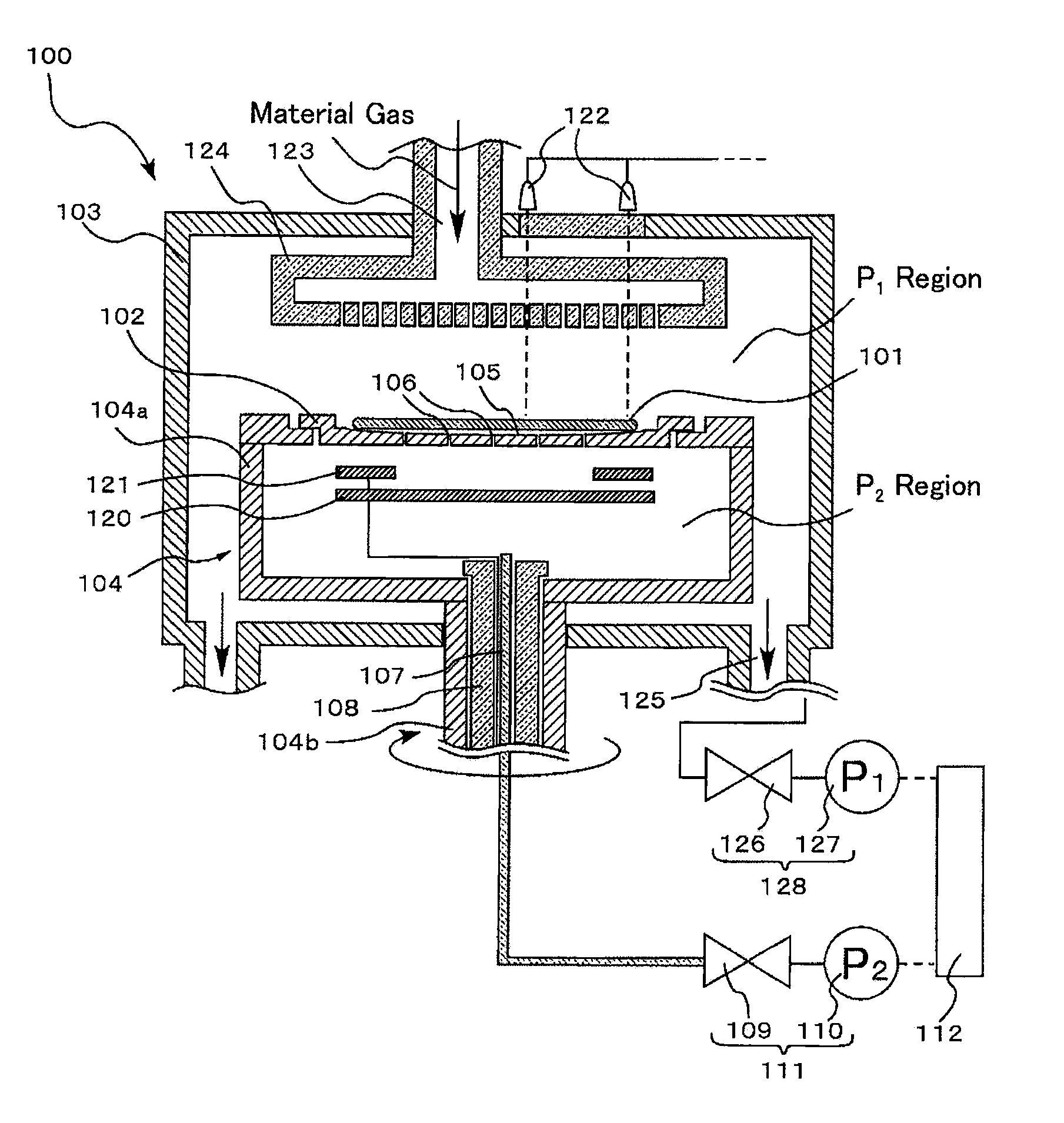
[0025]FIG. 1 is a schematic cross-sectional view of a coating apparatus 100 of a single wafer processing type according to an embodiment of the present invention. The substrate of the present embodiment described herein is a silicon wafer 101. However, the embodiment is not limited to this particular substrate, but may be applied to wafers of other suitable material depending on the application intended.

[0026]The coating apparatus 100 includes a chamber 103 serving as a coating chamber.

[0027]A gas supply portion 123 is provided above the chamber 103 to supply a material gas to the surface of the silicon wafer 101 in a heated state to form a crystalline coating on the surface. The gas supply portion 123 has connected thereto a shower plate 124 having a large number of material gas discharge holes formed therein. The shower plate 124 is disposed to face the surface of the silicon wafer 101 to supply material gas thereto.

[0028]A plurality of gas exhaust portions 125 are provided at the...


PUM

PropertyMeasurementUnit
Fractionaaaaaaaaaa
Temperatureaaaaaaaaaa
Pressureaaaaaaaaaa

Abstract

An object of the present invention is to provide a coating apparatus in which the substrate can be reliably rotated at high speed. Another object of the invention is to provide a coating method of forming a coating on a substrate while reliably rotating it at high speed. A coating apparatus includes a susceptor for supporting a silicon wafer, and a rotating portion for rotating the susceptor. The rotating portion is covered on top with the susceptor to form a P2 region. The contact surface of the susceptor with the silicon wafer has a plurality of holes therein. The silicon wafer is attached to the susceptor by evacuating gas from the P2 region.

Description

BACKGROUND OF THE INVENTION[0001]1. Field of the Invention[0002]The present invention relates to a coating apparatus and a coating method.[0003]2. Background Art[0004]Epitaxial growth techniques are conventionally used to manufacture semiconductor devices requiring a relatively thick crystalline coating or film, such as power devices, including IGBTs (Insulated Gate Bipolar Transistors).[0005]In order to produce an epitaxial wafer having a considerable coating thickness with high yield, it is necessary to bring new material gases one after another into contact with the uniformly heated surface of the wafer and thereby increase the coating speed. To do this, it is common practice that the wafer is subjected to epitaxial growth while it is rotated at high speed (see, e.g., Patent Document 1 below).[0006]According to Patent Document 1, the susceptor supporting the wafer thereon is fitted into a susceptor support, and the rotational shaft coupled to the susceptor support is rotated to r...

Claims


Application Information

Patent Timeline
IPC IPC(8): C23C16/44B05C11/00B05D3/12
CPCC23C16/4412C23C16/4584C23C16/4586H01L21/68785H01L21/6838H01L21/68735H01L21/67109
Inventor MORIYAMA, YOSHIKAZUNISHIKAWA, HIDEAKIYAJIMA, MASAYOSHIFURUTANI, HIROSHIMITANI, SHINICHINISHIBAYASHI, MICHIO
Owner NUFLARE TECH INC
Why Eureka
Try Eureka