Capacitor discharge ignition device for engine

a technology of capacitors and ignition devices, which is applied in the direction of machines/engines, mechanical equipment, lighting and heating apparatus, etc., can solve the problems of increasing the processing time required for voltage increasing circuit control, excessive charging voltage of ignition capacitors in the middle and high speed rotation areas of engines, and increasing the startability of the engine and stability of rotation, so as to increase the apparent trigger level of interruption control switches, increase the effect of ignition performance and reduced power consumption

Inactive Publication Date: 2009-11-05
KOKUSAN DENKI CO LTD
View PDF6 Cites 0 Cited by
  • Summary
  • Abstract
  • Description
  • Claims
  • Application Information

AI Technical Summary

Benefits of technology

[0015]An object of the present invention is to provide a capacitor discharge ignition device for an engine that prevents insufficient charging of an ignition capacitor during low speed rotation of the engine, and maintains a substantially constant output voltage of a voltage increasing circuit without wasting energy during middle and high speed rotation of the engine to prevent a charging voltage of the ignition capacitor from becoming excessive, without complex processings being performed by a microprocessor.

Problems solved by technology

Thus, when the voltage increasing circuit is comprised so as to charge the ignition capacitor to a predetermined voltage during low speed rotation of the engine, a charging voltage of the ignition capacitor becomes excessive in middle and high speed rotation areas of the engine.
However, providing such a voltage limiting circuit causes a large short-circuit current to pass from the exciter coil through the voltage limiting circuit during middle and high speed rotation of the engine, and thus the voltage limiting circuit wastes energy to increase heat generation from the exciter coil.
In the capacitor discharge ignition device disclosed in Japanese Patent Application Laid-Open Publication No. 5-52168, the arithmetical operation means for arithmetically operating the interruption timing of the voltage increasing switch with respect to the output voltage of the exciter coil and the rotational speed of the engine, and means for detecting the interruption timing arithmetically operated by the arithmetical operation means need to be constituted by a microprocessor, which increases the number of processings executed by the microprocessor for controlling the voltage increasing circuit, thereby inevitably increasing processing time required for control of the voltage increasing circuit.

Method used


Image

  • Capacitor discharge ignition device for engine
  • Capacitor discharge ignition device for engine
  • Capacitor discharge ignition device for engine

Examples


Embodiment Construction

[0030]Now, a preferred embodiment of the present invention will be described in detail with reference to the drawings. The present invention may be applied to an ignition device for igniting an engine having any number of cylinders, but for simplicity of description, the engine has a single cylinder in the embodiment described below.

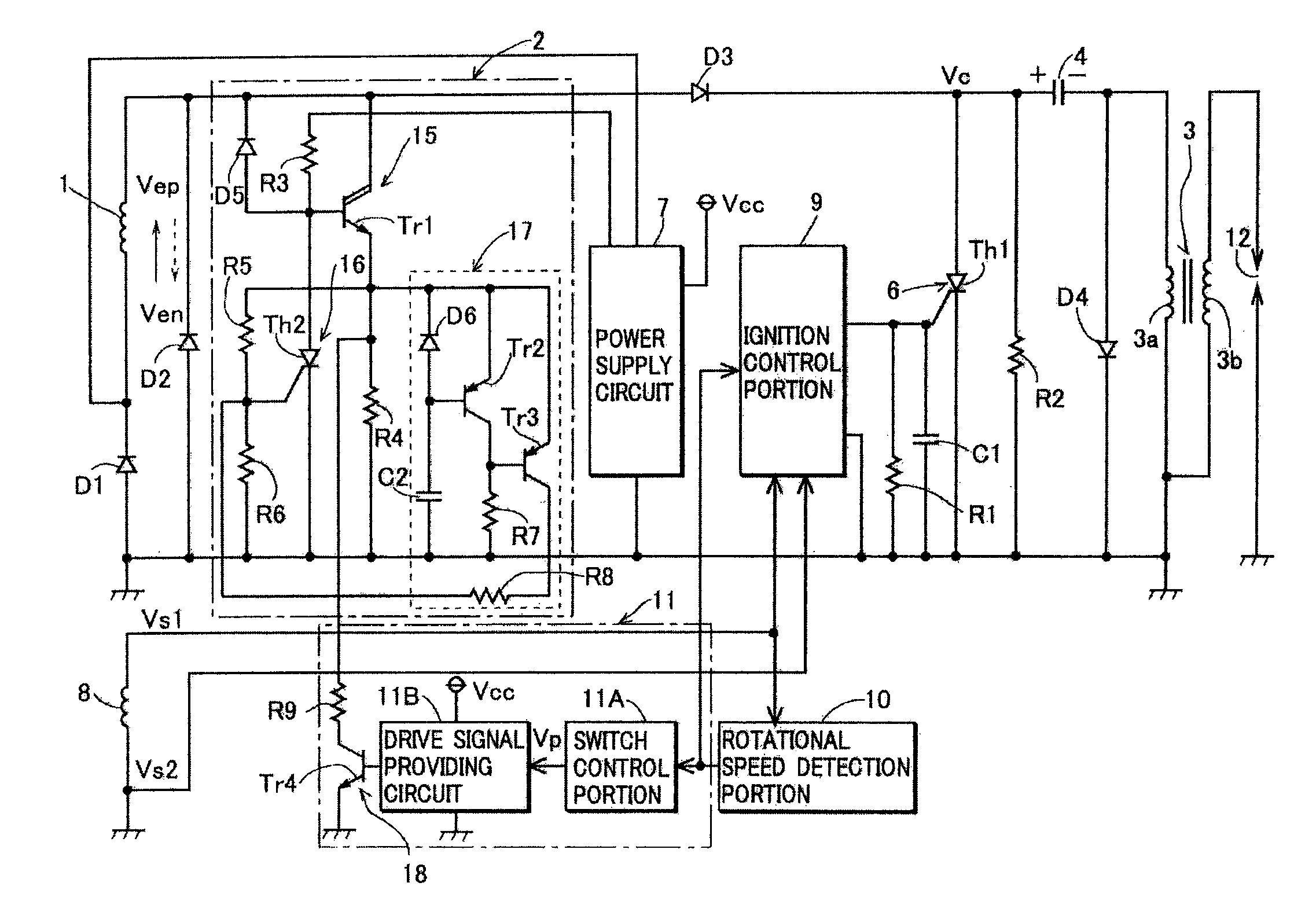
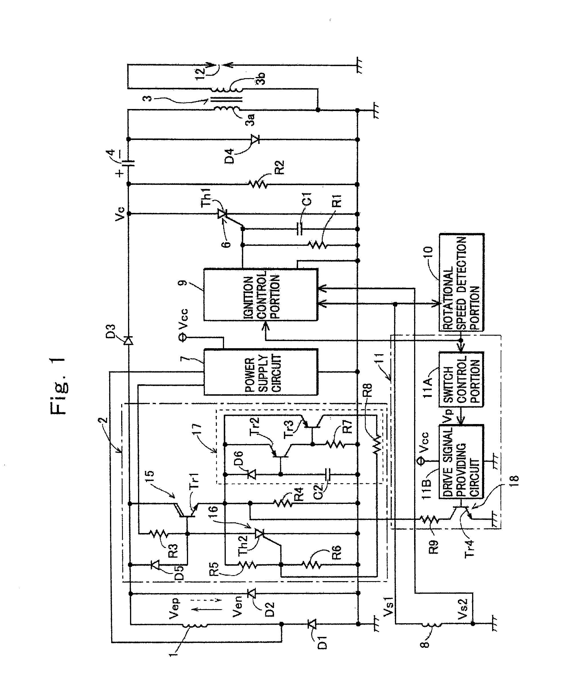
[0031]FIG. 1 shows a construction of the embodiment of the present invention. In FIG. 1, a reference numeral 1 denotes an exciter coil provided in a magneto AC generator mounted to an unshown engine, 2 denotes a voltage increasing circuit that increases an output voltage of one half cycle of the exciter coil 1, 3 denotes an ignition coil including a primary coil 3a and a secondary coil 3b each having one grounded end, 4 denotes an ignition capacitor provided on a primary side of the ignition coil and charged by an output of the voltage increasing circuit 2, 6 denotes a discharge switch that becomes an on-state when receiving an ignition signal and discha...


PUM


Abstract

A capacitor discharge ignition device for an engine including: an exciter coil provided in a magneto generator driven by the engine; a voltage increasing circuit that increases an induced voltage of the exciter coil; a capacitor charged by an output voltage of the voltage increasing circuit; and a discharge switch that is turned on at ignition timing of the engine and discharges charges in the capacitor through a primary coil of the ignition coil, wherein the ignition device further includes a voltage increasing control portion that controls the voltage increasing circuit so as to increase an output voltage of the voltage increasing circuit when a rotational speed of the engine is a set value or less, and limit the output voltage of the voltage increasing circuit when the rotational speed of the engine exceeds the set value.

Description

TECHNICAL FIELD OF THE INVENTION[0001]The present invention relates to a capacitor discharge ignition device that generates a high voltage for igniting an engine using an exciter coil provided in a magneto generator driven by the engine as a power supply.PRIOR ART OF THE INVENTION[0002]As well known, a capacitor discharge ignition device is comprised of a capacitor provided on a primary side of an ignition coil, a charging power supply for charging the capacitor, a capacitor discharge switch that is turned on when receiving an ignition signal and discharges charges in the capacitor through a primary coil of the ignition coil, and an ignition control portion that provides the ignition signal to the capacitor discharge switch at ignition timing of the engine.[0003]In such an ignition device, the charges in the capacitor are discharged through the primary coil of the ignition coil at the ignition timing of the engine to induce a high voltage for ignition in a secondary coil of the igni...

Claims


Application Information

Patent Timeline
Patent Type & Authority Applications(United States)
IPC IPC(8): F02P1/08F23Q3/00
CPCF02P1/086
Inventor SASAKI, KOUJI
Owner KOKUSAN DENKI CO LTD
Why Eureka
Try Eureka