Doherty power amplifier

a power amplifier and doherty technology, applied in the field of power amplifiers, can solve the problems of high production cost, the trend of increasing the size of the doherty amplifier, and the drawback of conventional methods for implementing such doherty amplifiers, so as to achieve the effect of improving efficiency and linearity, reducing production costs, and improving efficiency

Active Publication Date: 2009-11-05
WIPAM
View PDF5 Cites 6 Cited by
  • Summary
  • Abstract
  • Description
  • Claims
  • Application Information

AI Technical Summary

Benefits of technology

[0016]As described above, the present invention has advantageous effects in that it can provide an improved Doherty power amplifier capable of achieving a further miniaturization and integration while maintaining an advantage in terms of efficiency a

Problems solved by technology

When designing a Doherty amplifier for use in mobile communications, a limitation in size thereof is getting more important, and there is a trend of the Doherty amplifier getting more miniaturized.
However, conventional methods for implementing such Doherty amplifiers have drawbacks of high production costs due to the sizes of the chips and the packages thereof.
Most noticeably, quarter-wave transformers for controlling load line impedances of carrier amplifiers and 3 dB 90° hybrid splitters for dividing input powers are major causes of the increase in the production cost o

Method used


Image

  • Doherty power amplifier
  • Doherty power amplifier
  • Doherty power amplifier

Examples


first embodiment

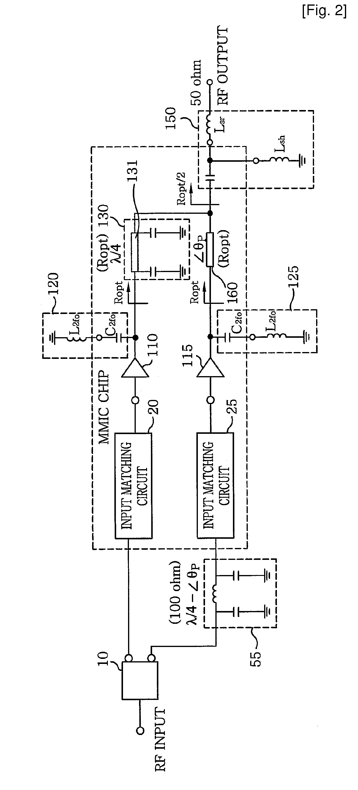
[0025]FIG. 2 illustrates a circuit diagram of a Doherty amplifier employing an output matching method in accordance with the present invention. Herein, identical reference numerals designate the same elements in comparison with FIG. 1.

[0026]If a quarter-wave transformer for controlling a load line impedance of a carrier amplifier in a Doherty amplifier is configured with a λ / 4 π-network composed of at least one inductor(s)(L) and at least one capacitor(s)(C) as shown in FIG. 1, it has drawbacks in terms of the chip size and power loss at the passive devices. In this case, one important factor is the inductance. In a conventional Doherty amplifier shown in FIG. 1, a characteristic impedance of the quarter-wave transformer arranged at an output end of the carrier amplifier is equal to 100 Ohm. Further, the inductance corresponding thereto is obtained by the equation of L=Z0 / ω0. As seen therefrom, the quarter wave transformer can be implemented by using an inductor of a smaller inducta...

second embodiment

[0034]FIG. 3 provides a circuit diagram of a Doherty amplifier employing the input matching method in accordance with the present invention. Herein, identical reference numerals designate the same elements in comparison with FIG. 2.

[0035]Referring to FIG. 3, the Doherty amplifier of the present embodiment includes a plurality of output matching circuits 40 and 45; a λ / 4 π-network 50; a carrier and a peaking amplifier 110 and 115; a second delay circuit 140; a power dividing circuit 145; an offset line 160; and a plurality of input matching circuits 170 and 175. More specifically, the carrier and the peaking amplifier 110 and 115 are arranged in parallel, and the output matching circuits 40 and 45 are connected to output ends of the carrier and the peaking amplifier 110 and 115, respectively. The λ / 4 π-network 50 is connected, as an impedance control circuit, to an output end of the output matching circuit 40 arranged at an output end of the carrier amplifier 110 for adjusting a load...

third embodiment

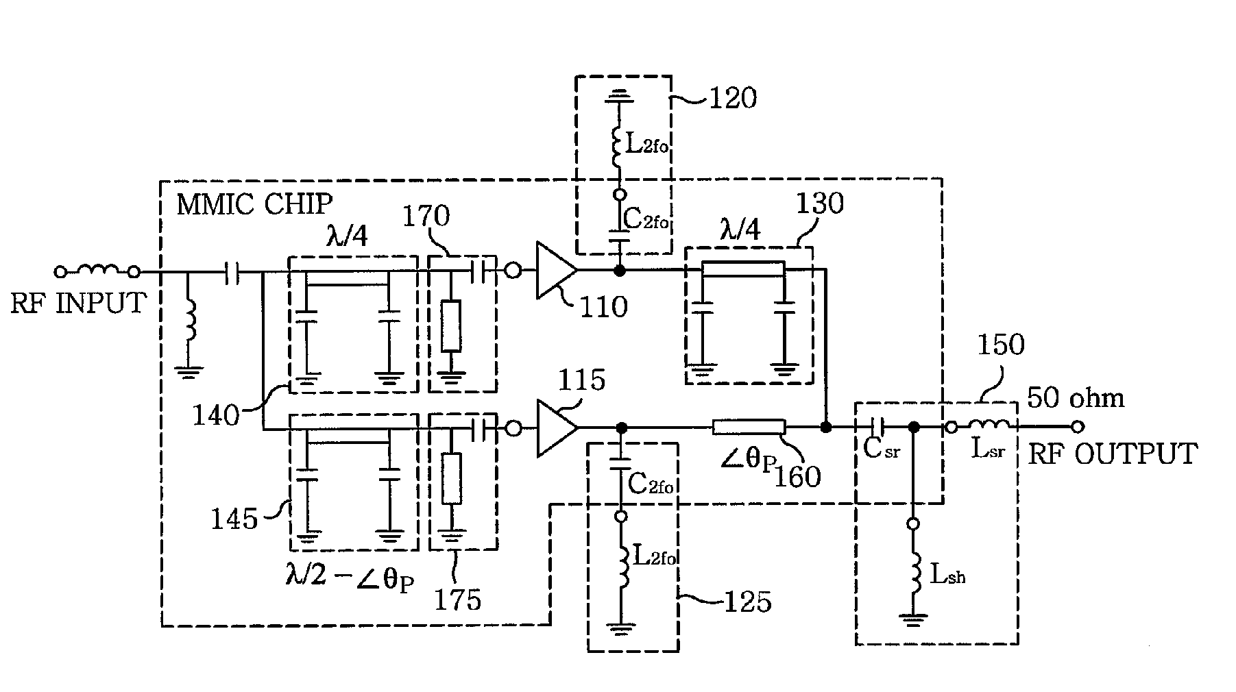
[0038]FIG. 4 illustrates a circuit diagram of a Doherty amplifier in accordance with the present invention, to which both the input and the output matching method of the present invention are applied. Herein, identical reference numerals designate the same elements in comparison with FIGS. 2 and 3.

[0039]Referring to FIG. 4, the Doherty amplifier in accordance with the third embodiment of the present invention includes a carrier amplifier 110; a peaking amplifier 115; an impedance control circuit 130; a second delay circuit 140; a power dividing circuit 145; an output matching circuit 150; and a plurality of input matching circuits 170 and 175. The carrier amplifier 110 and the peaking amplifier 115 are arranged in parallel, and the input matching circuits 170 and 175 are connected to input ends of the carrier and the peaking amplifier 110 and 115, respectively. The impedance control circuit 130 is connected to an output end of the carrier amplifier 110 for adjusting the load line im...


PUM


Abstract

The present invention relates to a power amplifier; and, more particularly, to a Doherty power amplifier. The power amplifier includes at least one carrier amplifier; at least one peaking amplifier arranged in parallel with the carrier amplifier in such a manner that the carrier amplifier and the peaking amplifier collectively operate as a Doherty amplifier; a plurality of input matching circuits, at least one of which is respectively connected to an input ends of the carrier amplifier and the peaking amplifier; at least one impedance control circuit, each of which is connected to an output end of each carrier amplifier for controlling a load line impedance of the said each carrier amplifier; at least one output matching circuit directly or indirectly connected to output ends of the impedance control circuit and the peaking amplifier; and at least one first delay circuit for matching delays between the carrier amplifier and the peaking amplifier. The present invention provides an improved Doherty power amplifier capable of achieving a further miniaturization and integration while maintaining an advantage in terms of efficiency and linearity of a Doherty power amplifier by employing an improved output and input matching method, and capable of operating more similar to the ideal operation of a Doherty power amplifier by applying an improved input power division method thereto.

Description

TECHNICAL FIELD[0001]The present invention relates to a power amplifier, and more particularly, to a Doherty power amplifier capable of being integrated on a chip by miniaturization thereof.BACKGROUND ART[0002]As efforts to extend usable time of batteries in mobile handsets, repeaters and base stations used for mobile communications while they are getting more miniaturized and multifunctional, lots of researches have been done recently to improve the efficiencies of RF power amplifiers that occupies most of the power consumption. Especially, researches on a Doherty power amplifier as one of typical schemes for enhancing the efficiency of a power amplifier are actively progressing.[0003]As well-known in the art, a Doherty power amplifier, which was first designed in 1936 by W. H. Doherty, has a structure that connects a carrier amplifier and a peaking amplifier in parallel by using a quarter-wave transformer, i.e., a λ / 4 line. The Doherty amplifier is driven by a symmetrical power co...

Claims


Application Information

Patent Timeline
IPC IPC(8): H03F1/07
CPCH03F1/0288H03F3/195H03F2200/451H03F2200/255H03F2200/423H03F3/602H03F1/07
Inventor YU, DAE-KYU
Owner WIPAM
Why Eureka
Try Eureka