Injection/stretch blow molding machine

a technology of injection/stretch blowing machine and molding machine, which is applied in the direction of dough shaping, manufacturing tools, food shaping, etc., can solve the problems of difficult adoption of injection mold clamping mechanism, large amount of oil used in hydraulic circuits, and inability to carry molding machine into interior, so as to achieve the effect of significantly improving the working efficiency of mold replacement and easy assembling of molds

Active Publication Date: 2009-11-05
A K TECH LAB INC
View PDF5 Cites 7 Cited by
  • Summary
  • Abstract
  • Description
  • Claims
  • Application Information

AI Technical Summary

Benefits of technology

[0017]In this construction, since edge sides of the portions of the upper base platen corresponding to the operation sections and edge sides of the portions of the transfer platen to be stopped at the operation sections are each formed as a U-shaped recess of a size permitting insertion therein of a joint plate, the work for mounting injection core molds, blow cores and stretching rods onto the upper base platen can be perfo

Problems solved by technology

In such an injection mold clamping mechanism, since the mold clamping cylinder block is fixed to the upper ends of the tie bars, the height of the mechanism is larger than that of the ordinary vertical type mold clamping mechanism, and in a certain workshop the molding machine cannot be carried into the interior.
Moreover, since all of mold opening, closing and clamping works are performed by hydraulic means, the amount of oil used in hydraulic circuits is very large.
Besides, since hydraulic cylinders are located higher than the upper base platen, there is a fear of contamination caused by oil leakage and thus there is the problem that the adoption of the injection mold clamping mechanism is difficult for s

Method used


Image

  • Injection/stretch blow molding machine
  • Injection/stretch blow molding machine
  • Injection/stretch blow molding machine

Examples


Embodiment Construction

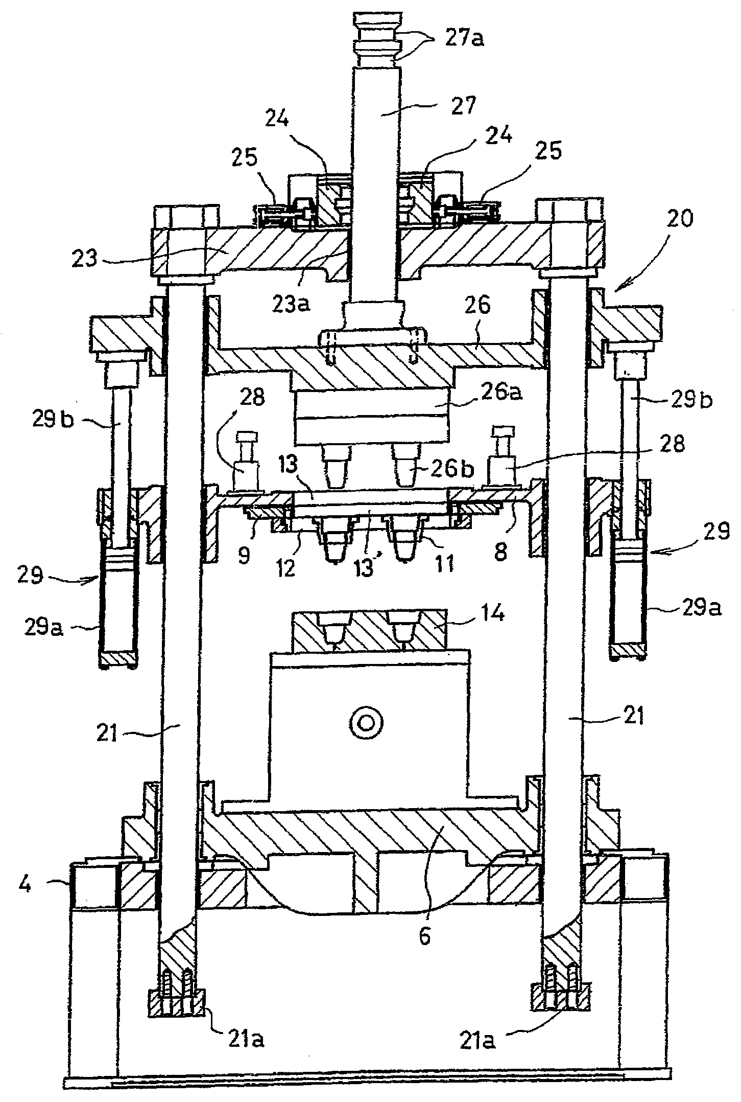
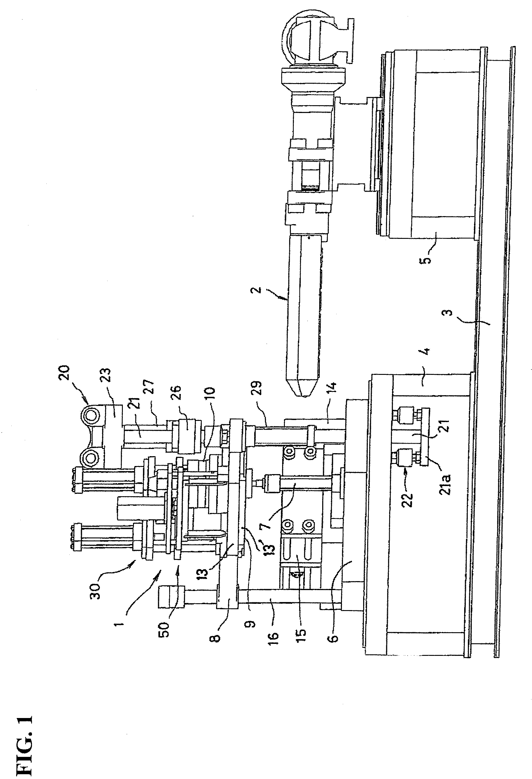
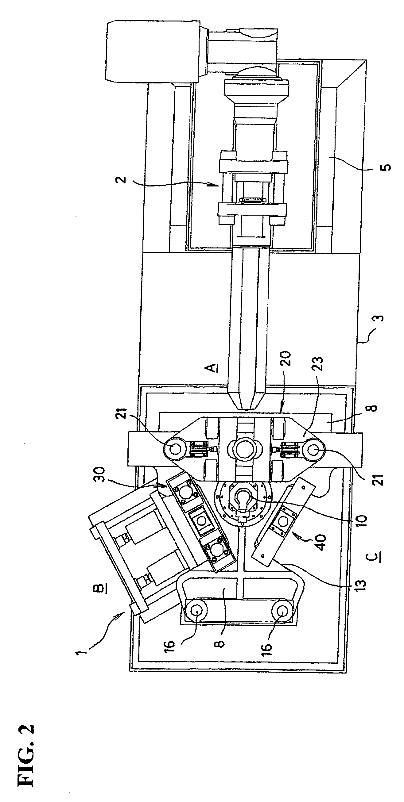
[0030]In the drawings, the numeral 1 denotes an injection / stretch blow unit and numeral 2 denotes an injection unit. These are respectively installed on dedicated beds 4 and 5 for each having a frame structure. The beds 4 and 5 are dividedly placed and fixed onto a common base frame 3 while ensuring a predetermined work space therebetween.

[0031]The injection / stretch blow unit 1 includes a lower base platen 6 installed on the bed 4 and an upper base platen 8 supported horizontally above the lower base platen 6 by a hydraulic lift cylinder 7. A circular transfer platen 9 is attached to an underside of the upper base platen 8 and connected rotatably to a drive shaft of an electric motor 10 which is installed in the center of an upper surface of the upper base platen 8. The drive motor 10 is an AC servomotor adapted to rotate intermittently by 120 degrees. At a lower surface of an edge portion of the transfer platen 9, as shown in FIG. 3 et seq., a mold holding plate 12 comprising a pai...


PUM


Abstract

Provided is an injection/stretch blow molding machine, which performs both injection molding of a preform and stretch blow molding of a hollow molded product continuously within single machine. In an injection/stretch blow unit used in the injection/stretch blow molding machine, an injection mold clamping mechanism comprises a mold clamping shafts erected vertically movably on both sides of an injection molding operation section and extending through both a lower base platen and an upper base platen, hydraulic mold clamping means connected respectively to lower ends positioned within a bed of the mold clamping shafts, a mold clamping platen having core molds attached thereto downwards and being fitted and supported at both ends thereof on the mold clamping shafts, the mold clamping platen being installed vertically movably between the upper base platen and a top platen disposed on upper ends of the shafts, a pair of mold opening/closing air cylinders connecting on both sides thereof the upper base platen and the mold clamping platen with each other and causing the mold clamping platen to move vertically with respect to the upper base platen, a mold clamping rod connected to the mold clamping platen through the top platen, and a pair of clamp members disposed on an upper surface of the top platen, the clamp members being adapted to fit with the mold clamping rod pneumatically to connect the mold clamping platen and the mold clamping shafts with each other. In an injection molding operation section, a stretch blow molding operation section and a take-out operation section, edge sides of the upper base platen and a transfer platen are formed as U-shaped recesses and neck molds are positioned within the recesses by bridgewise mounting of mold holding plates over the recesses.

Description

FIELD OF THE INVENTION[0001]The present invention relates to an injection / stretch blow molding machine which performs both injection molding of a preform and stretch blow molding of a hollow molded product such as, for example, a bottle in a continuous manner within single machine by intermittent rotation of a transfer platen disposed above a machine base.DESCRIPTION OF THE BACKGROUND ART[0002]In this type of a molding machine, both injection unit and injection / stretch blow unit are installed on single bed. The injection / stretch blow unit is horizontally provided with a base platen on which installed are an injection mold clamping mechanism and a stretch blowing mechanism, the base platen being positioned above a lower base platen installed on a bed. As examples of such an upper base platen, there are known a movable one supported vertically movably by a hydraulic lift cylinder as is disclosed in Japanese Patent Laid-Open Publication No. 2004-122440 and a stationary one as is disclo...

Claims


Application Information

Patent Timeline
IPC IPC(8): B29C49/06
CPCB29C45/0053B29C45/1769B29C49/36B29C49/062B29C49/12B29C49/06B29C2049/023B29C2949/0715
Inventor KOBAYASHI, SENTAROMATSUZAKA, NAOHIDE
Owner A K TECH LAB INC
Why Eureka
Try Eureka