Load drive device and vehicle equipped with the same

a technology of load drive and load circuit, which is applied in the direction of dynamo-electric converter control, pulse technique, instruments, etc., can solve the problems of increased switching loss, reduced surge voltage, deterioration of etc., and achieves improved fuel efficiency, reduced switching loss of the drive circuit, and improved fuel efficiency of the vehicle equipped with the load drive device

Inactive Publication Date: 2009-11-12
TOYOTA JIDOSHA KK
View PDF5 Cites 45 Cited by
  • Summary
  • Abstract
  • Description
  • Claims
  • Application Information

AI Technical Summary

Benefits of technology

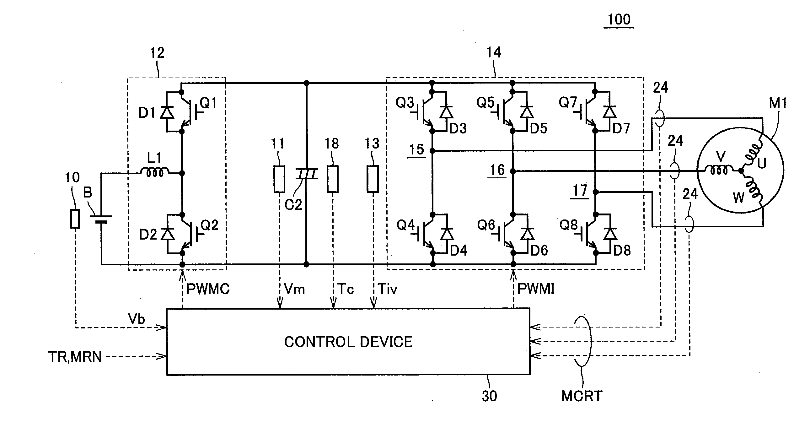
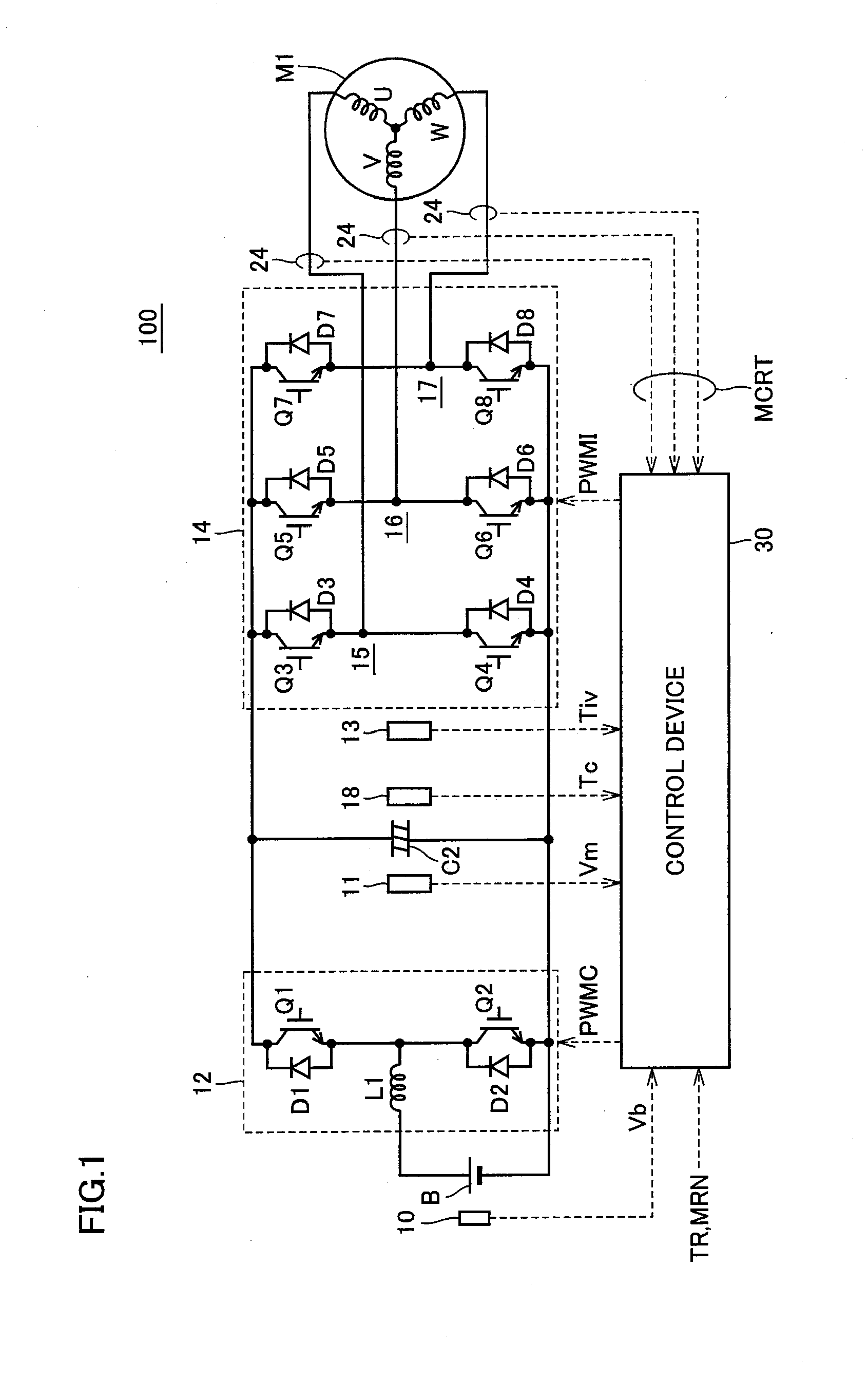
[0015]According to the load drive device described above, when the upper limit value of the input voltage of the drive circuit is set depending on the temperature of the capacity element, the allowable range of the surge voltage superimposed on the input voltage can be ensured irrespective of the temperature of the capacity element. Consequently, the switching loss of the drive circuit can be reliably reduced.
[0036]According to the present invention, the switching loss of the drive circuit can be reliably reduced, with the result that the fuel efficiency of the vehicle equipped with the load drive device according to the present invention can be improved.

Problems solved by technology

However, reduction in the switching speed leads to not only a decrease in the surge voltage but also an increase in the switching loss, which produces a problem of deterioration in fuel efficiency of the vehicle.
Thus, in the low temperature environment, the allowable range of the surge voltage is strictly limited and the switching loss is difficult to be suppressed.
According to the control device for the electric vehicle disclosed in Japanese Patent Laying-Open No. 2001-169407 described above, however, in the region where the power element is relatively low in temperature, while the increased input resistance value of the power element causes suppression of the surge voltage generation and allows prevention of breakdown of the power element, there is still a problem that the decrease in the switching speed results in an increase in the switching loss.

Method used


Image

  • Load drive device and vehicle equipped with the same
  • Load drive device and vehicle equipped with the same
  • Load drive device and vehicle equipped with the same

Examples


modification 1

[0115][Modification 1]

[0116]FIG. 9 is another flowchart describing the control of input voltage Vm of inverter 14 in accordance with the embodiment of the present invention.

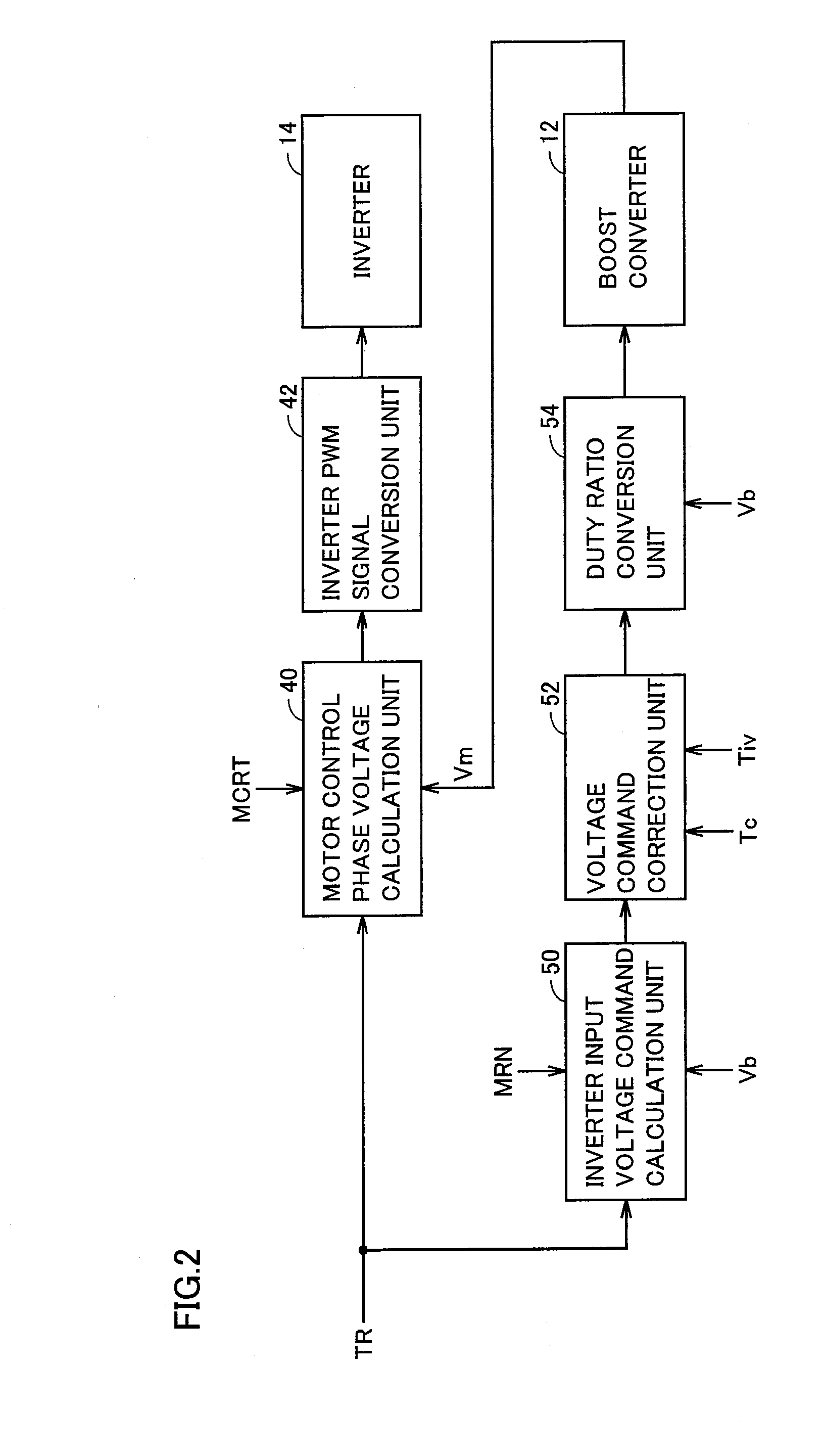
[0117]The flowchart shown in FIG. 9 is modified such that the variable control of input voltage Vm depending on capacitor temperature Tc in the flowchart shown in FIG. 7 is performed depending on inverter temperature Tiv.

[0118]Referring to FIG. 9, when a series of operations are started, inverter input voltage command calculation unit 50 calculates voltage command Vdc_com that is a target value of inverter input voltage Vm based on torque command value TR and motor rotation speed MRN from the external ECU. The calculated voltage command Vdc_corn is output to voltage command correction unit 52 (step S01).

[0119]Voltage command correction unit 52 receives voltage command Vdc_com from inverter input voltage command calculation unit 50, receives capacitor temperature Tc from temperature sensor 18 and receives inverter...

modification 2

[0124][Modification 2]

[0125]FIG. 10 is another flowchart describing the control of input voltage Vm of inverter 14 in accordance with the embodiment of the present invention.

[0126]The flowchart shown in FIG. 10 is modified such that the variable control of input voltage Vm depending on capacitor temperature Tc in the flowchart shown in FIG. 7 is performed depending on capacitor temperature Tc and inverter temperature Tiv.

[0127]Referring to FIG. 10, when a series of operations are started, inverter input voltage command calculation unit 50 calculates voltage command Vdc_com that is a target value of inverter input voltage Vm based on torque command value TR and motor rotation speed MRN from the external ECU, and outputs the calculated voltage command Vdc_com to voltage command correction unit 52 (step S01).

[0128]Voltage command correction unit 52 receives voltage command Vdc_com from inverter input voltage command calculation unit 50, receives capacitor temperature Tc from temperatur...


PUM


Abstract

A surge voltage generated by the switching operation of an IGBT element and voltage variation generated in an equivalent series resistance of a capacitor are superimposed on an input voltage of an inverter. The equivalent series resistance has a temperature dependence that a resistance value increases with a decrease in a capacitor temperature. The IGBT element has a temperature dependence that an element withstand voltage decreases with a decrease in an inverter temperature. When capacitor temperature is lower than a predetermined threshold value, a control device reduces an upper limit value of the input voltage by an amount corresponding to the voltage variation from its upper limit value at a high temperature, and controls a target voltage of a boost converter such that an output voltage does not exceed the upper limit value. Consequently, the allowable range of the surge voltage can be ensured.

Description

TECHNICAL FIELD[0001]The present invention relates to a load drive device and a vehicle equipped with the load drive device, and more particularly to a load drive device capable of reducing the switching loss of a drive circuit and a vehicle equipped with the load drive device.BACKGROUND ART[0002]Vehicles such as electric vehicles (EV) and hybrid vehicles (HV) generally obtain the driving force from electric energy by using an inverter to convert the direct-current (DC) power supplied from a high voltage battery into a three-phase alternating-current (AC) power, causing a three-phase AC motor to be rotated. During the deceleration of the vehicle, the regenerative energy obtained by regeneration of the three-phase AC motor is stored in the battery, causing the vehicle to run without wasting the energy.[0003]In the above-described hybrid vehicle or electric vehicle, the inverter is provided with six switching elements (for example, IGBT (Isolated Gate Bipolar Transistor)) having three...

Claims


Application Information

Patent Timeline
Patent Type & Authority Applications(United States)
IPC IPC(8): H02M7/5387
CPCB60L3/12Y02T10/92B60L11/1872B60L2210/14B60L2240/525H02M7/797H02M2001/0048H02P2201/09H03K17/14H03K2017/0806Y02T10/642Y02T10/7005Y02T10/7022Y02T10/705Y02T10/7225B60L11/005B60L50/40B60L58/25H02M1/0048Y02T10/64Y02T10/70Y02T10/72
Inventor HAMATANI, TAKASHI
Owner TOYOTA JIDOSHA KK
Why Eureka
Try Eureka