Device and Method for Improved Pile Casting

a technology of improved pile casting and casting device, which is applied in the direction of bulkheads/piles, construction, foundation engineering, etc., can solve the problems of soil shrinkage, unevenness, and cracks that can be several meters deep

a technology of improved pile casting and casting device, which is applied in the direction of bulkheads/piles, construction, foundation engineering, etc., can solve the problems of soil shrinkage, unevenness, and cracks that can be several meters deep

US20090279960A1Inactive Publication Date: 2009-11-12HAZZAN BASEM

Image

  • Device and Method for Improved Pile Casting
  • Device and Method for Improved Pile Casting
  • Device and Method for Improved Pile Casting

Examples


Embodiment Construction

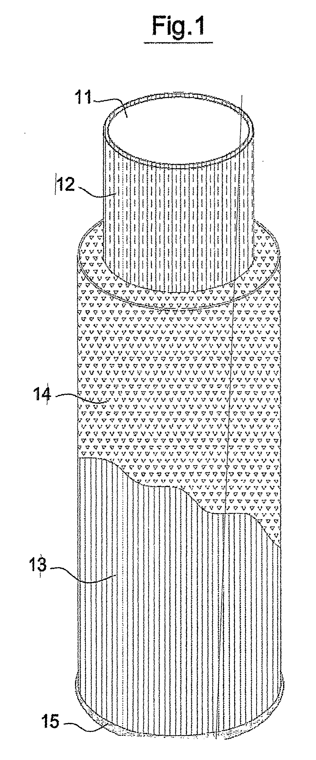
[0034]FIG. 1 is a view depicting some of the elements of this inventive device 11, and should be preferably viewed in conjunction with FIGS. 2, 3, 4, 9 and 11.

[0035]FIG. 1 depicts 12, a relatively thick and rigid inner sleeve having an inner diameter, a thickness, and a length, said thickness could be typically 1 to 5 mm but is not limited to this range. Several of many possible materials for 12 are polypropylene, PVC, HDPE and cardboard, 14 is a filling sleeve of a preferably relatively low density, low elastic modulus, highly deformable material such as a plastic or other foam, of which the widely used low density polystyrene foam (Styrofoamâ„¢) is a typical example, an outer sleeve 13 is of a relatively thin and preferably smooth, low friction coefficient material for sliding on 14, each of sleeves 12, 13, 14 having substantially the same length and two extremities, sleeve 12 is encompassed by sleeve 14 and sleeve 14 is encompassed by sleeve 13. Two sealing rings 15, a bottom one (...


PUM


Abstract

This invention deals with a device and a method for an improved concrete pile casting in swelling soils by substantially lowering or eliminating heave forces created in active soils from affecting said piles by surrounding selectable parts of the pile by an easily deformable material for lowering the horizontal and the vertical soil movement effect, and by providing a low friction surface for further lowering vertical forces effect. This inventive device and method further facilitates subsequent operations by permitting an easy and seamless casting of columns and by ensuring a clean and smooth pile surface for a better adhesion of new concrete to an old one, as well as preventing cement dough seepage to surrounding soil and concrete segregation.

Description

FIELD OF THE INVENTION[0001]This invention deals with a device for the neutralization, i.d. the lowering or the elimination, of heave forces acting on piles sunk in certain types of expansive soils and for the improvement of the properties of cast in situ piles.BACKGROUND OF THE INVENTION[0002]Certain types of soils, such as clay and marl, swell when absorbing water and shrink when this water is exuded. Water is usually absorbed by soils during the rainy season and exuded by evaporation and the like during the dry season. The shrinkage leads to cracks which can be several meters deep and ten centimeters wide, depending on many factors. The soil depth in which this phenomenon occurs is called the active depth hereinbelow, and may not be uniform. In a rainy season following a dry one, water tends to flow into the cracks and leads to soil swelling, which also closes the cracks, and in the following dry season the soil shrinks to create cracks. Thus an annual soil shrinkage-swelling cyc...

Claims


Application Information

Patent Timeline
12 Nov 2009
Publication
US20090279960A1
IPC
E02D5/00; E02D5/58
CPC
E02D5/64
Inventors
HAZZAN, BASEM