Method and device for operating an internal combustion engine

a technology of internal combustion engine and method, which is applied in the direction of electrical control, process and machine control, instruments, etc., can solve the problems of increasing undesired hydrocarbon emissions, for example, and achieve the effects of reducing undesired emissions, reducing undesired emissions, and reducing undesired emissions

Active Publication Date: 2009-11-12
ROBERT BOSCH GMBH
View PDF4 Cites 37 Cited by
  • Summary
  • Abstract
  • Description
  • Claims
  • Application Information

AI Technical Summary

Benefits of technology

[0008]The method according to the present invention and the device according to the present invention for operating an internal combustion engine offer the advantage that a ratio between the first fuel quantity and the second fuel quantity is continuously modified as a function of the temperature. This enables a fluid transition between the portion of the first fuel quantity and the portion of the second fuel quantity of the setpoint fuel quantity to be injected for different temperatures that are characteristic for the operation of the internal combustion engine as a function of the temperature, so that the operation of the internal combustion engine is able to be optimized with regard to reducing undesired emissions, e.g., of hydrocarbons, during the start, as well with regard to preventing knocking and self-ignitions.
[0009]It is advantageous if at a first temperature value the first fuel quantity is selected smaller than the second fuel quantity, and at a second temperature value that is greater than the first temperature value, it is advantageous if the first fuel quantity is selected greater than the second fuel quantity. This makes it possible for the direct injection to outweigh the intake manifold injection given dropping engine or ambient temperatures in the cold start. This reduces the wall film formation for the lower temperature range of the cold start, so that no increased fuel injection is required and the undesired emissions are able to be reduced. For the upper temperature range of the cold start, on the other hand, the intake manifold injection outweighs the direct injection, so that the undesired emissions are reduced by the satisfactory homogenization of the air / fuel mixture due to the predominant intake manifold injection.
[0010]It is also advantageous if at a third temperature value that is greater than the second temperature value, the first fuel quantity is selected smaller than the second fuel quantity. This ensures that, once again, the direct injection outweighs the intake manifold injection in the warm start of the internal combustion engine, so that the knocking and self-ignition tendencies are less pronounced.
[0011]A further advantage results if the second fuel quantity is subdivided into a first partial quantity to be injected during an intake stroke, and into a second partial quantity to be injected during a compression stroke as a function of the temperature. In this way the share of the direct injection is able to be optimally adapted to the temperature that is characteristic for the operation of the internal combustion engine, with respect to lower undesired emissions as well as reduced knocking and self-ignition tendencies.
[0012]In this context it is advantageous if the subdivision of the second fuel quantity into the first partial quantity and into the second partial quantity is modified continuously as a function of the temperature. This enables a fluid transition between the first partial quantity to be injected and the second partial quantity to be injected, as a function of the temperature, thereby improving the adaptation of the operation of the internal combustion engine to the engine temperature or ambient temperature with respect to reducing undesired emissions and reducing any knocking and self-ignition, in particular during the start of the internal combustion engine.
[0013]In addition, it is advantageous if the first partial quantity is selected to increase with rising temperatures and if the second partial quantity if selected to decrease with rising temperatures. This ensures that in the lower temperature range of the cold start the direct injection predominantly occurs during the compression stroke. Thus, an injection takes place into already compressed, and therefore heated, air of the combustion chamber. This results in better evaporation of the directly injected fuel. In the lower temperature range of the cold start, the fuel quantity to be injected is thus able to be reduced considerably, which in turn decreases the undesired emissions. On the other hand, for the temperature range of the warm start, it can be ensured that the predominant share of the direct injection takes place during the intake stroke, so that the temperatures in the combustion chamber are reduced in this manner because of the cooling fuel, thereby reducing the knocking and self-ignition tendencies.

Problems solved by technology

As a consequence, the undesired emissions of hydrocarbons, for example, rise during the start of the internal combustion engine.

Method used


Image

  • Method and device for operating an internal combustion engine
  • Method and device for operating an internal combustion engine
  • Method and device for operating an internal combustion engine

Examples


Embodiment Construction

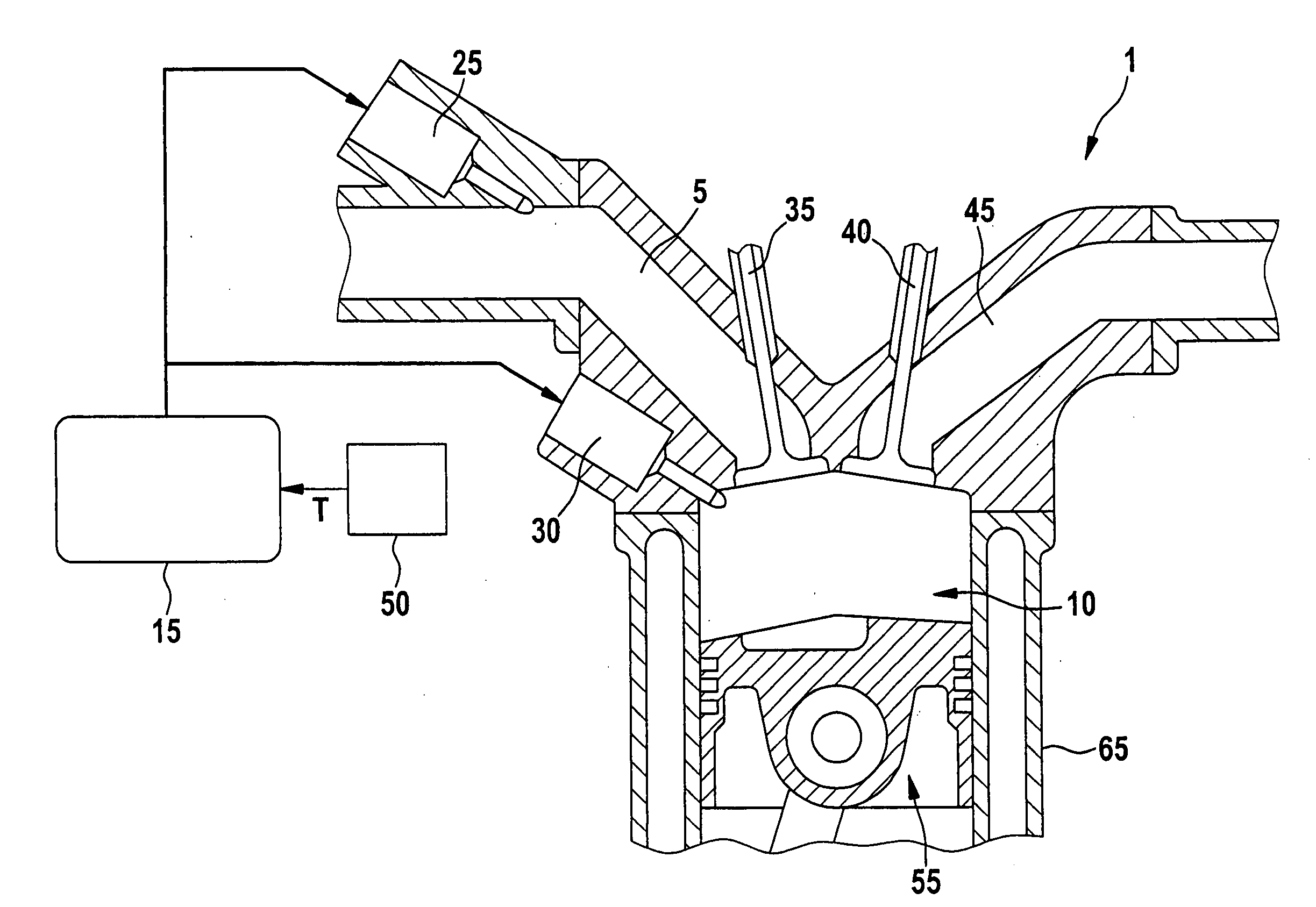
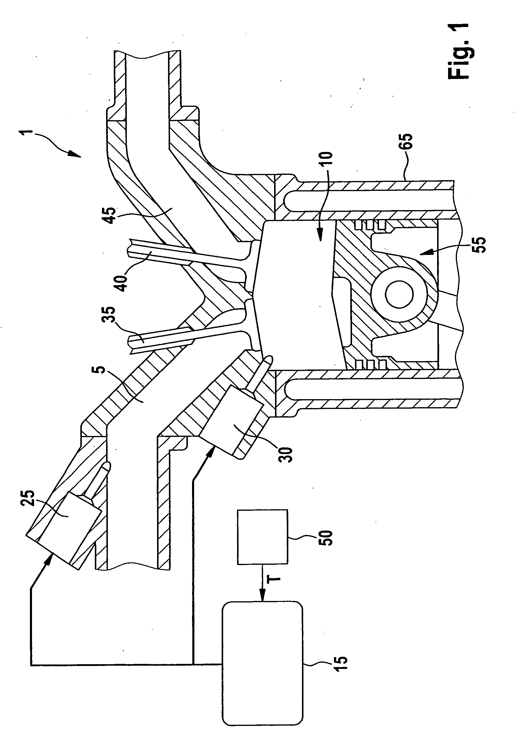
[0021]In FIG. 1, reference numeral 1 denotes an internal combustion engine, which may take the form of a spark-ignition engine or a diesel engine. Internal combustion engine 1 includes one or a plurality of cylinder(s) 65, one of which is shown in FIG. 1 by way of example. Fresh air is able to be supplied to a combustion chamber 10 of cylinder 65 via an intake manifold 5. Furthermore, intake manifold 5 is able to be supplied with fuel via a first fuel injector 25. The air / fuel mixture thus produced in intake manifold 5 is forwarded to combustion chamber 10 via a fuel injector 35 during an intake stroke of cylinder 65. It is also possible to supply fuel directly into combustion chamber 10 via a second fuel injector 30. The exhaust gas formed in combustion chamber 10 during the combustion of the air / fuel mixture is expelled into an exhaust tract 45 during an exhaust stroke via a discharge valve 40. The combustion of the air / fuel mixture in combustion chamber 10 sets a piston 55 of cyl...


PUM


Abstract

In a method for operating an internal combustion engine, a setpoint fuel quantity to be injected is subdivided into a first fuel quantity which is to be injected into an intake manifold of the internal combustion engine, and a second fuel quantity to be injected directly into a combustion chamber of the internal combustion engine. The subdivision of the fuel quantity is performed as a function of a temperature that is characteristic for the operation of the internal combustion engine, e.g., in a start of the internal combustion engine, and the ratio between the first fuel quantity and the second fuel quantity is continually modified as a function of the temperature.

Description

BACKGROUND OF THE INVENTION[0001]1. Field of the Invention[0002]The present invention relates to a method and a device for operating an internal combustion engine, in which a setpoint fuel-injection quantity is subdivided.[0003]2. Description of Related Art[0004]Already known in the art are methods and devices for operating an internal combustion engine, in which a setpoint fuel quantity to be injected is subdivided into a first fuel quantity to be injected into an intake manifold, and into a second fuel quantity to be injected directly into a combustion chamber of the internal combustion engine, as a function of a temperature that is characteristic for the operation of the internal combustion engine in a start of the internal combustion engine. Depending on the engine temperature characteristic for the operation of the internal combustion engine, for example, a distinction is made between a cold start and a warm start of the internal combustion engine. In the cold start, it is know...

Claims


Application Information

Patent Timeline
Patent Type & Authority Applications(United States)
IPC IPC(8): F02D41/30F02B3/00
CPCF02D35/025F02D41/0025F02D41/047F02D2200/023F02D41/3094F02D41/402F02D41/062F02D2200/021
Inventor MALLEBREIN, GEORGEFRANK, MICHAELSCHWEINSBERG, ALEXANDER SCHENCK ZUKEMMER, HELERSONSAMENFINK, WOLFGANG
Owner ROBERT BOSCH GMBH
Why Eureka
Try Eureka