Centering a part inside a shaft

a technology for centering parts and shafts, which is applied in the direction of bearing units, rigid supports of bearing units, forging/pressing/hammering apparatus, etc., can solve the problems of affecting the working efficiency of the machine, affecting the quality of the machine, and requiring special tooling. it is relatively expensive, and the positioning of rings is wrong. , to achieve the effect of simple, effective and inexpensiv

Active Publication Date: 2009-11-19
SN DETUDE & DE CONSTR DE MOTEURS DAVIATION S N E C M A
View PDF6 Cites 21 Cited by
  • Summary
  • Abstract
  • Description
  • Claims
  • Application Information

AI Technical Summary

Benefits of technology

[0011]A particular object of the invention is to provide a simple, inexpensive, and effective solution to the above-mentioned problems, enabling the drawbacks of the prior art to be avoided.

Problems solved by technology

For this purpose, known centering rings are generally mounted by force using systems of the type comprising screws and spreaders, which can lead to the rings being wrongly positioned and can damage the inside surface of the shaft.
In addition, mounting such rings requires special tooling that is relatively expensive.
Furthermore, known centering rings are too bulky to be suitable for use in turbojets of small size, typically jets having a fan of diameter less than forty inches, i.e. about one meter.

Method used


Image

  • Centering a part inside a shaft
  • Centering a part inside a shaft
  • Centering a part inside a shaft

Examples


first embodiment

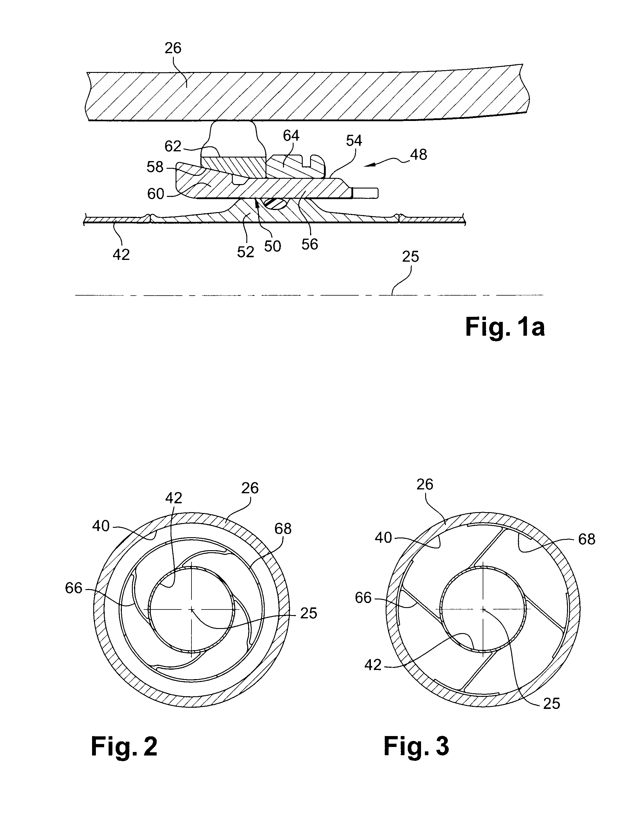
[0059]In the invention, shown in FIGS. 2 and 3, the deformable means are rods 66 made of shape-memory material capable of presenting a single shape material effect, such as a for example an alloy of nickel and titanium, sometimes known as nitinol.

[0060]Each rod 66 is substantially radial or obliquely inclined relative to a radius, and has a radially inner end fastened to the outside surface of the tube 42, e.g. by welding or brazing, and a radially outer end carrying a bearing shoe 68 constituted by an annular sector of a common material, such as steel, for the purpose of being pressed against the inside surface 40 of the shaft 26, the shoe 68 being fastened to the rod 66 likewise by welding, brazing, or the like.

[0061]In the retracted configuration shown in FIG. 2, the radially outer ends of the rods 66 are curved inwards so that the shoes 68 are located at a short distance from the tube 42 adjacent to one another, thereby forming a ring that is substantially continuous.

[0062]In th...

second embodiment

[0070]FIGS. 4 and 5 show the invention in which the deformable means of the centering device comprise a ring 70 made of a shape-memory material that is capable of presenting a double shape-memory effect, such as an alloy of the CuAlNi, CuZnAl, CuAlBe, NiTi, or indeed NiTiNb type, so as to make it possible both to deploy and to retract the device by heating or cooling it.

[0071]In order to implement the double shape-memory effect, the ring 70 is initially subjected to a training stage comprising a series of thermomechanical cycles in which it is shaped in alternation to have a circular shape, at a temperature below the transition temperature Tt of the shape-memory material to the austenitic phase, such that this material is then in its martensitic phase, and into an oval shape by lengthening the ring in a plane 72 containing the axis 25 of the shaft 26, at a temperature higher than the transition temperature Tt of the shape-memory material, such that the material is in its austenitic ...

third embodiment

[0082]In a third embodiment shown in FIGS. 6 and 7, the deformable means comprise plates 84 of shape-memory material suitable for presenting a double shape-memory effect, which plates are interposed between a ring 86 and bearing shoes 88.

[0083]The ring 86, e.g. made of a common material such as steel, includes hollow portions or cups 90 formed in its outside surface and regularly distributed around the axis 25 of the ring, there being four of these cups 90, for example.

[0084]By way of example, each cup 90 is frustoconical in shape with a flat bottom, and it designed to house a bearing shoe 88 of substantially complementary shape, e.g. made of a material analogous to that of the ring 86, together with a plate 84 of shape-memory material that is interposed between the bearing shoe 88 and the bottom of the cup 90 and that is configured to push the bearing shoe 88 radially outwards on being subjected to a temperature higher than the transition temperature Tt of the shape-memory material...


PUM

PropertyMeasurementUnit
transition temperature Ttaaaaaaaaaa
diameteraaaaaaaaaa

Abstract

A device for centering a tube inside a hollow shaft, the device comprising deformable means interposed between the tube and the hollow shaft and including bearing members for bearing against the inside surface of the shaft and suitable for being spaced away from the inside surface of the shaft in order to enable them to be moved inside the shaft, the deformable means being made of a shape-memory material suitable for deforming to press the bearing members against the inside surface of the shaft or to space them away therefrom on being subjected to a predetermined temperature.

Description

FIELD OF THE INVENTION[0001]The present invention relates to a device for centering a part inside a shaft, in particular in a turbomachine such as an airplane turbojet.BACKGROUND OF THE INVENTION[0002]In bypass turbojets, the shaft of the low-pressure turbine is hollow and may contain a tube, commonly referred to as a “center vent” tube that serves to connect the bearings supporting the low-pressure rotor to the outside atmosphere so as to discharge a flow of oil-laden air towards the downstream end of the turbojet.[0003]In general, this tube extends over the entire length of the rotor shaft and its ends are constrained to rotate together with the shaft.[0004]Given its long length and its relatively thin wall, the tube is conventionally supported by one or more centering rings that include means for bearing against the inside wall of the shaft.[0005]Nevertheless, in order to improve the dynamic behavior of the turbojet, the low-pressure compressor shaft generally has an inside diame...

Claims


Application Information

Patent Timeline
Patent Type & Authority Applications(United States)
IPC IPC(8): B23P15/04
CPCF01D5/085F01D25/12F01D25/125F01D25/28Y02T50/671Y02T50/676Y10T29/53961F05D2230/64F05D2240/61F05D2300/505Y10T29/53978Y10T29/4932Y10T29/49998F05D2230/60Y02T50/60
Inventor MONS, CLAUDE MARCELRABERIN, LAURENTRONGVAUX, JEAN-MARCROUSSELIN, STEPHANE
Owner SN DETUDE & DE CONSTR DE MOTEURS DAVIATION S N E C M A
Why Eureka
Try Eureka