Configurations And Methods For LNG Fueled Power Plants

a technology of lng and power plants, applied in the direction of machines/engines, mechanical equipment, containers, etc., can solve the problems of increasing global natural gas consumption, reducing the efficiency of vaporization, and increasing the cost of vaporization, so as to reduce the condensation of steam and improve the power output.

Inactive Publication Date: 2009-11-19
FLUOR TECH CORP
View PDF12 Cites 18 Cited by
  • Summary
  • Abstract
  • Description
  • Claims
  • Application Information

AI Technical Summary

Benefits of technology

[0009]The present invention is directed to combined cycle power plants with integrated LNG regasification in which power output is significantly improved by using refrigeration content in the LNG to deep chill intake air, typically below the freezing point of water, and to lower the steam condensation temperature and the pressure at the surface condenser of the steam driven power cycle. Intake air chilling is most preferably performed using two precoolers that operate in alternating manner such that one precooler is deiced using heated heat transfer fluid when the other precooler cools intake air using cooled heat transfer fluid.

Problems solved by technology

Thus, it is not surprising that global consumption of natural gas is projected to increase substantially in the coming years, and that the anticipated demand may not be met by domestic production.
Unfortunately, vaporization is an energy intensive process and typically requires a heat duty representing about 2 to 3% of the energy content in the LNG.
While conventional LNG regasification facilities typically require an external heat source (e.g., seawater heater), the heat for vaporization may also be provided by a combustion process in a synergistic manner.
However, these processes are typically limited to cool the intake air to 40° F.
Still further, and among yet other difficulties, heat transfer in some of these configurations is often limited by the freezing of water.
Moreover, dislodging of ice particles from the turbine inlet tends to damage the gas turbine and disrupts power generation.
Moreover, while the currently known gas turbine air pre-cool methods improve power generation efficiencies in hot climate regions (e.g., in the tropics or sub-tropics), they are often not suitable to colder climate regions (e.g., northeastern parts of North America).
Even in relatively hot climate, such configurations provide efficiency benefits only in the summer months, with decreasing benefits in the winter seasons.
Therefore, while numerous processes and configurations for power plants with LNG utilization and / or regasification are known in the art, all of almost all of them suffer from one or more disadvantages.

Method used


Image

  • Configurations And Methods For LNG Fueled Power Plants
  • Configurations And Methods For LNG Fueled Power Plants
  • Configurations And Methods For LNG Fueled Power Plants

Examples


Embodiment Construction

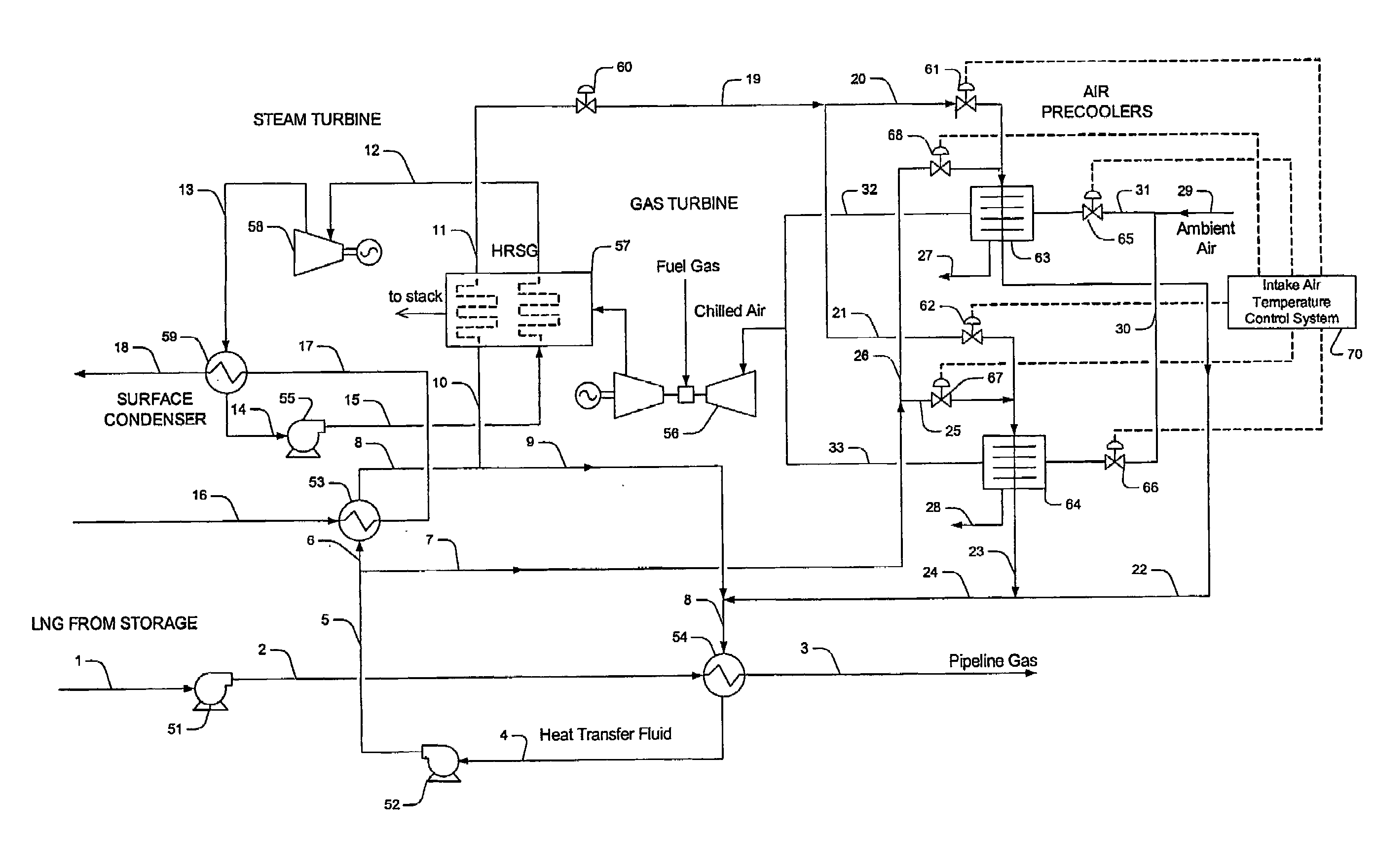
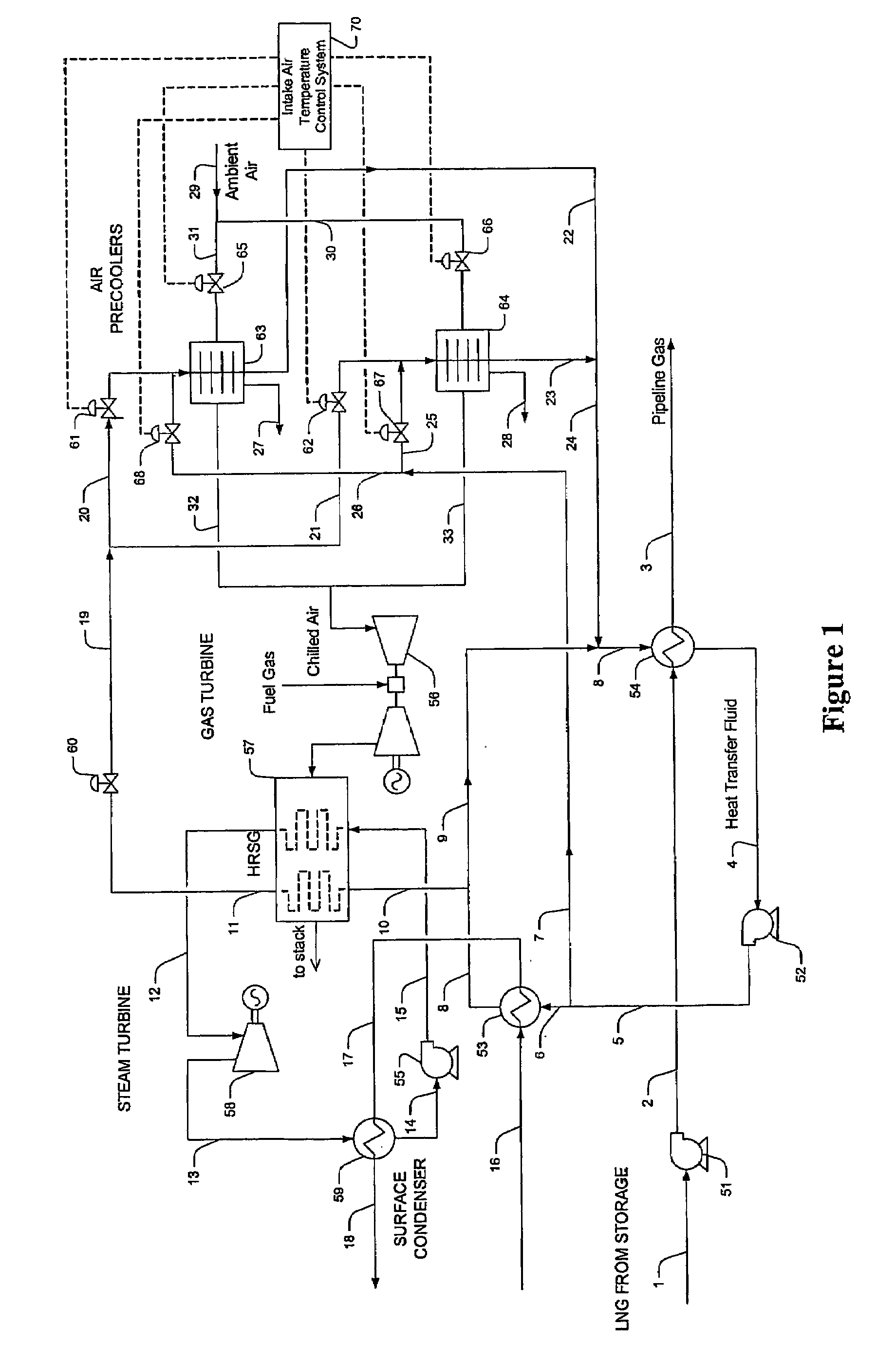
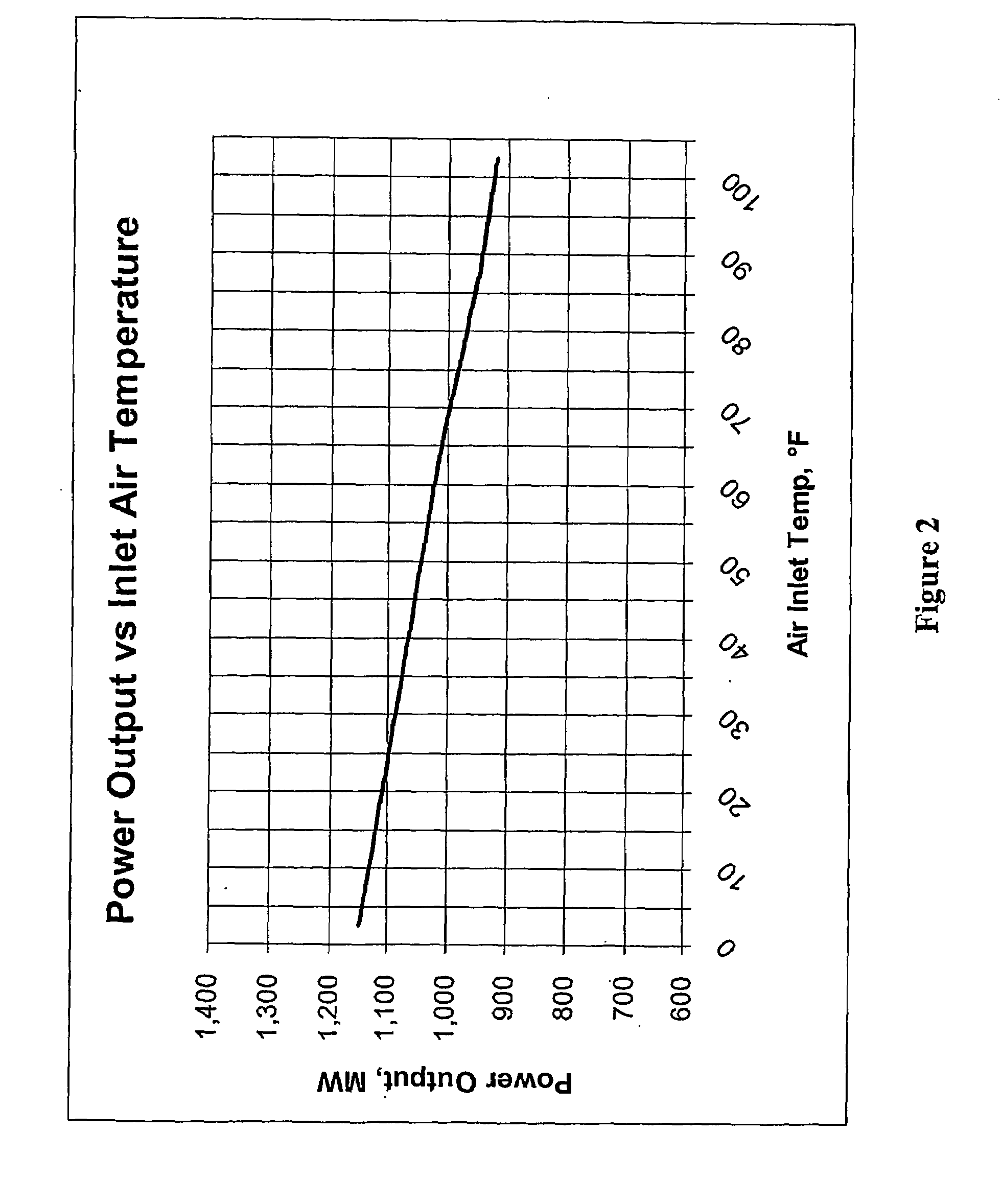
[0021]The inventor discovered that power output and efficiency in a combined cycle power plant can be substantially increased in a seasonally independent manner by integrating power generation with extraction of refrigeration content in LNG.

[0022]More specifically, LNG is regasified in a LNG regasification unit to thereby cool a heat transfer fluid. A first portion of the cooled heat transfer fluid is then used in a precooler to provide deep chilling of combustion turbine intake air to a temperature below 50° F., more typically below 32° F., and most typically below 0° F., while a second portion is used to cool the cooling water supplied to the working fluid (e.g., expanded steam) in a power cycle. The so warmed heat transfer fluid is further heated (e.g., in a HRSG) and then employed to deice frozen condensate formed in the precooler. Most typically, a second precooler is employed to maintain continuous operation of the combustion turbine and operated in an alternating manner with ...


PUM


Abstract

Contemplated configurations and methods use first and second precoolers, preferably in alternating operation, to provide a combustion turbine with air at a temperature of 50° F., and more typically less than 32° F. and most typically less than 0° F. In such configurations and methods it is generally preferred that a heat transfer fluid circuit provides both, heated and cooled heat transfer fluid to thereby allow cooling and deicing of the precoolers. Most preferably, refrigeration is provided from an LNG regasification unit to form the cooled heat transfer fluid while heat from a power cycle (e.g., from surface condenser) is used to form the heated heat transfer fluid.

Description

[0001]This application claims priority to our copending U.S. provisional patent applications with the Ser. Nos. 60 / 637,860 and 60 / 660,000, which were filed Dec. 20, 2004 and Mar. 8, 2005, respectively, and which are incorporated by reference herein.FIELD OF THE INVENTION[0002]The field of the invention is integrated power generation using Liquefied Natural Gas (LNG), and especially power generation in LNG regasification facilities.BACKGROUND OF THE INVENTION[0003]LNG has recently gained significant attention as an alternative clean energy source as the cost of crude oil has reached historic highs. Thus, it is not surprising that global consumption of natural gas is projected to increase substantially in the coming years, and that the anticipated demand may not be met by domestic production. Natural gas shortage is further compounded by the retirement of older power plants and replacement with more efficient combined cycle power plants. To satisfy at least part of the increasing LNG ...

Claims


Application Information

Patent Timeline
Patent Type & Authority Applications(United States)
IPC IPC(8): F02C7/143F02C7/16F02C7/057F17C9/02
CPCF01K9/003F01K23/10F02C3/22F02C6/18Y02E20/16F02C7/143F02C7/18F17C2227/0323F17C2265/05F02C7/12
Inventor MAK, JOHN
Owner FLUOR TECH CORP
Why Eureka
Try Eureka