Reflective collection-type light receiving unit and light receiving apparatus for spatial light communications

Active Publication Date: 2009-11-19
PLANNERS LAND
View PDF6 Cites 14 Cited by
  • Summary
  • Abstract
  • Description
  • Claims
  • Application Information

AI Technical Summary

Benefits of technology

[0022]According to the present invention, the plurality of reflective collection-type light receiving units mounted on one sheet of the circuit substrate can be further decreased in thickness to downsize the light receiving apparatus. It is also possible to further reduce an electrostatic capacitance generated between a pair of electrode leads and the ground of the circuit substrate as compared with a case where a light receiving element is simply connected to the input side of a preamplifier or the like on a circuit substrate and also improve the high-speed responsiveness of the light receiving element.
[0023]As described so far, the reflective collection-type light receiving unit of the present invention is able to receive spatial light which contains visible light or infrared light at a high light receiving

Problems solved by technology

However, in wireless communications in which radio waves are used as a medium, it is impossible to increase the transmission power, with the influence of electromagnetic waves on the human body taken into account, where the transmitting and receiving are performed near people.
Further, since the frequency range of radio waves used in wireless communications has already been allocated in many areas and actually used, it is impossible to use freely frequencies over a wide range.
Still further, under special circumstances such as medical institutions, there are some restrictions, for example, the limited use of radio waves.
In particular, in visible light communications movable in a relative position between the transmitter and the receiver, in order to increase a light collecting percentage of light, with consideration given to a case where light radiated from the projector of the transmitter is lower in the amount of light arriving at a light receiving unit o

Method used


Image

  • Reflective collection-type light receiving unit and light receiving apparatus for spatial light communications
  • Reflective collection-type light receiving unit and light receiving apparatus for spatial light communications
  • Reflective collection-type light receiving unit and light receiving apparatus for spatial light communications

Examples


Embodiment Construction

[0029]Hereinafter, a description will be given to an embodiment of the present invention with reference to the drawings. In addition, the present invention shall not be limited to the embodiment. Any modification within requirements of the claims or equivalents of the requirements shall be included within the scope of the claims.

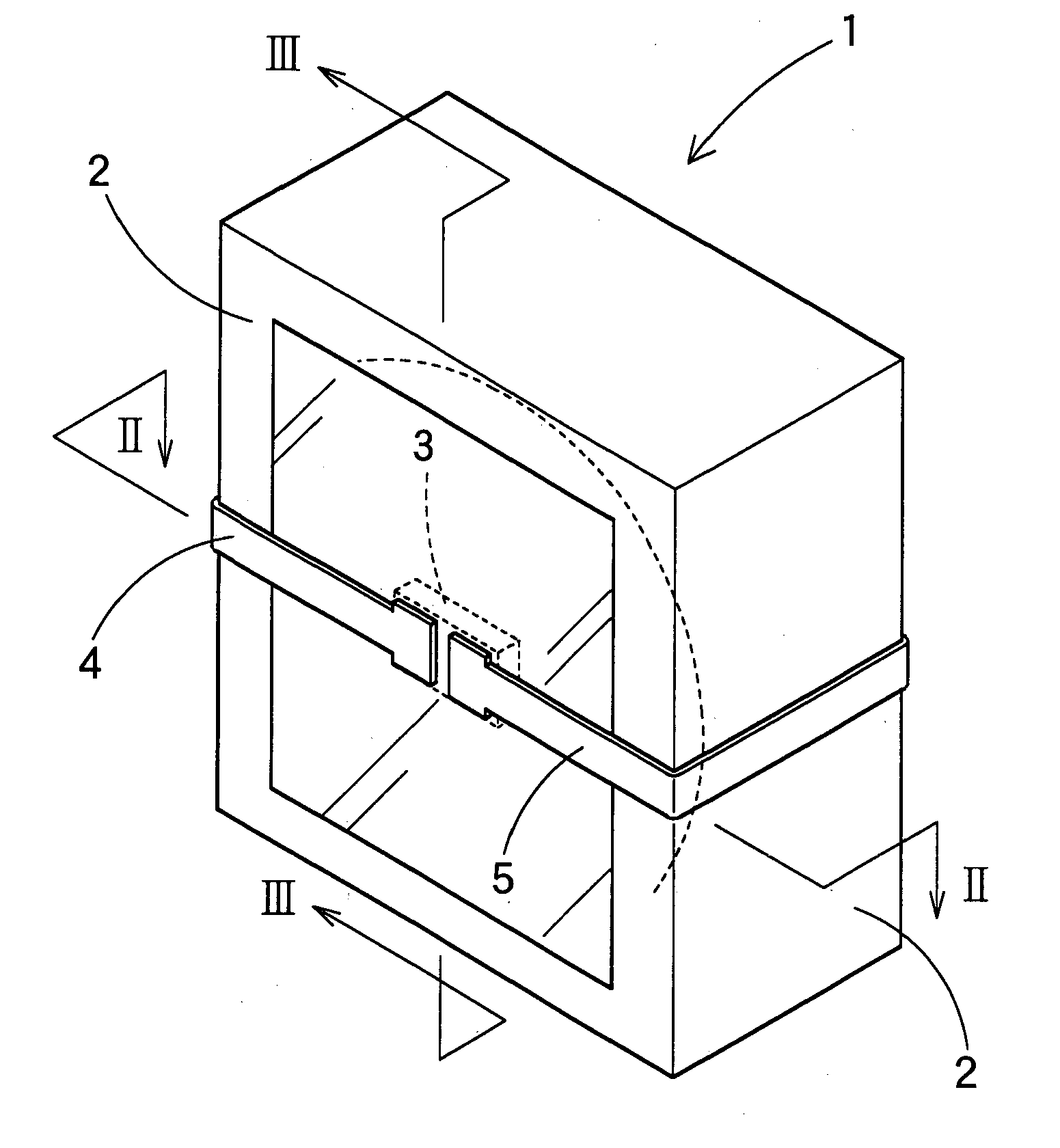
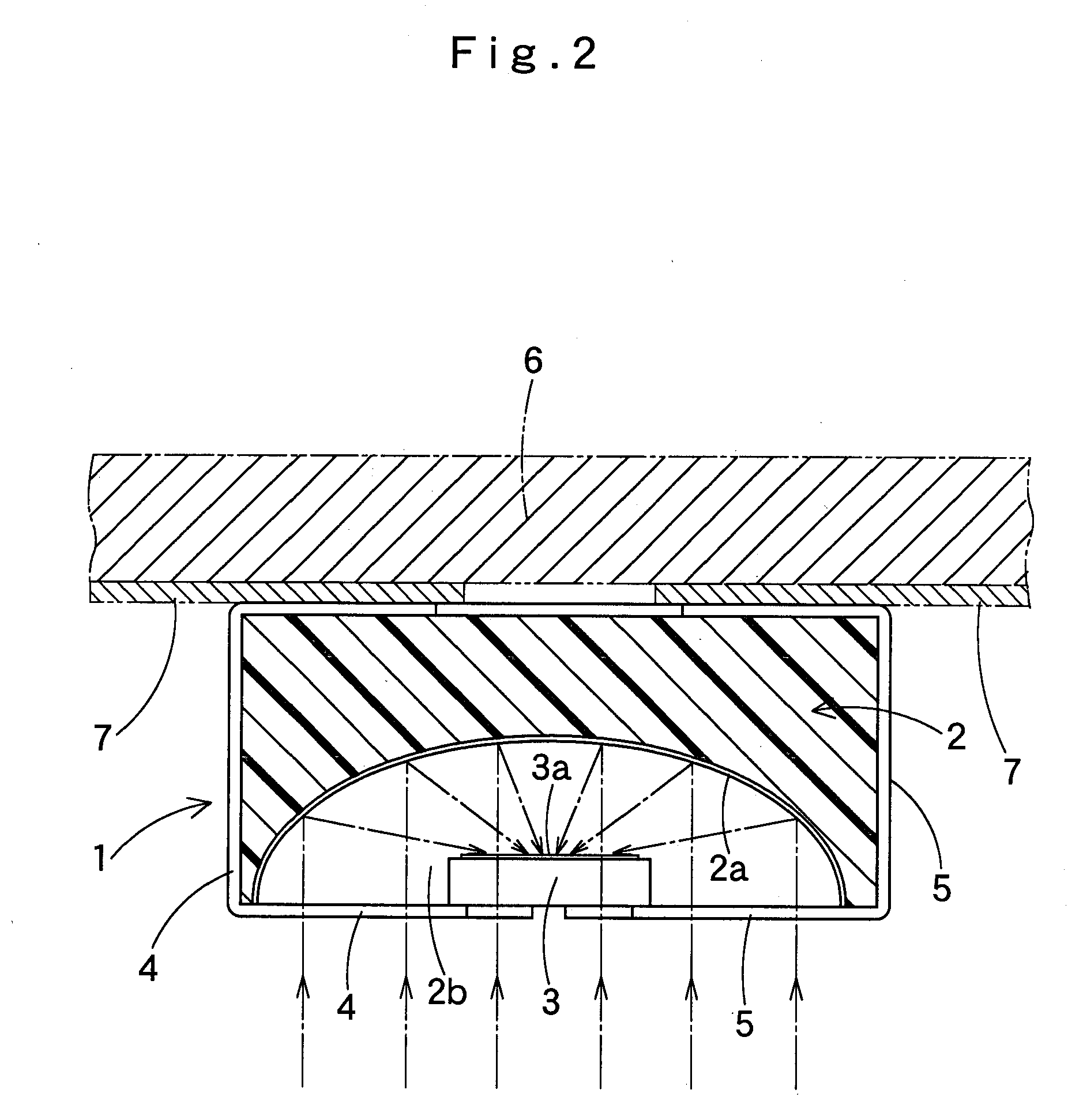
[0030]FIG. 1 is an enlarged perspective view of a reflective collection-type light receiving unit 1 for spatial light communications, and FIG. 2 is an enlarged cross sectional view thereof. In brief, the reflective collection-type light receiving unit 1 is a light receiving unit which reflects and collects via a concave mirror 2 spatial light projected and illuminated from a transmitter (not illustrated) to receive the light by a light receiving element 3, in which a light receiving element 3 is arranged approximately at the center inside the concave mirror 2, with a light receiving plane 3a thereof facing to a reflecting plane 2a of the concave mirror 2. A ...


PUM


Abstract

The reflective collection-type light receiving unit of the present invention is a reflective collection-type light receiving unit having a light receiving element which receives spatial light on which an information signal is superimposed after being reflected and collected via a concave mirror. The light receiving element is arranged approximately at the center inside the concave mirror, with the light receiving plane thereof facing to the reflection plane of the concave mirror. A pair of electrode leads connected to both electrodes of the light receiving element are extended so as to be opened from the center on the front plane of the concave mirror to both sides and connected to a light receiving circuit by way of the lateral plane of the concave mirror.

Description

BACKGROUND OF THE INVENTION[0001]1. Field of the Invention[0002]The present invention relates to a reflective collection-type light receiving unit and a light receiving apparatus for spatial light communications using the reflective collection-type light receiving unit and more particularly to a reflective collection-type light receiving unit for spatial light communications for performing communications using visible light or infrared light radiated in a space and a light receiving apparatus for spatial light communications in which a plurality of reflective collection-type light receiving units are arranged in an array to realize communications higher in sensitivity and responsiveness.[0003]2. Description of Related Art[0004]Wireless communications by using radio waves as a communication medium have found many uses in various fields such as cellular phone networks, wireless LANs and short-distance wireless communications.[0005]However, in wireless communications in which radio wav...

Claims


Application Information

Patent Timeline
IPC IPC(8): G01J5/00H01J40/14H01L31/02
CPCH01L31/0203H04B10/1149H01L31/02327H01L31/02H04B10/11H04B10/67
Inventor MURAYAMA, FUMITAKAKUROKAWA, HIROYUKI
Owner PLANNERS LAND
Why Eureka
Try Eureka