Projection objective of a microlithographic projection exposure apparatus

a technology of exposure apparatus and projection objective, which is applied in the direction of photomechanical apparatus, polarising elements, instruments, etc., can solve problems such as objective obscuration, and achieve the effect of reducing the obscuration caused by high-index optical materials

Active Publication Date: 2009-11-19
CARL ZEISS SMT GMBH
View PDF3 Cites 35 Cited by
  • Summary
  • Abstract
  • Description
  • Claims
  • Application Information

AI Technical Summary

Benefits of technology

[0014]It is therefore an object of the invention to provide a projection objective of a microlithographi

Problems solved by technology

Variations of this optical property

Method used


Image

  • Projection objective of a microlithographic projection exposure apparatus
  • Projection objective of a microlithographic projection exposure apparatus
  • Projection objective of a microlithographic projection exposure apparatus

Examples


Embodiment Construction

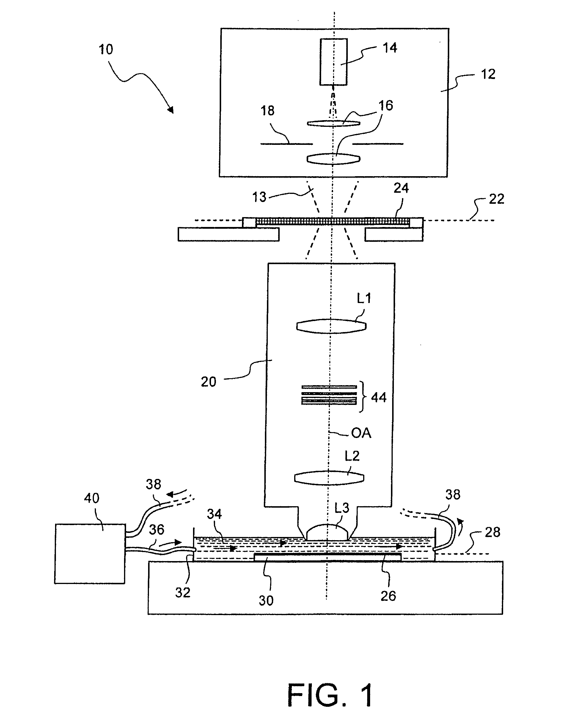
[0059]FIG. 1 is a schematic meridional section through a microlithographic projection exposure apparatus which is denoted in its entirety by 10. The projection exposure apparatus 10 comprises an illumination system 12 for generating projection light 13, which includes a light source 14, illumination optics indicated by 16 and a field stop 18. In the embodiment shown the projection light has a wavelength of 193 nm. As a matter of course, other wavelengths, for example 157 nm or 248 nm, are also contemplated.

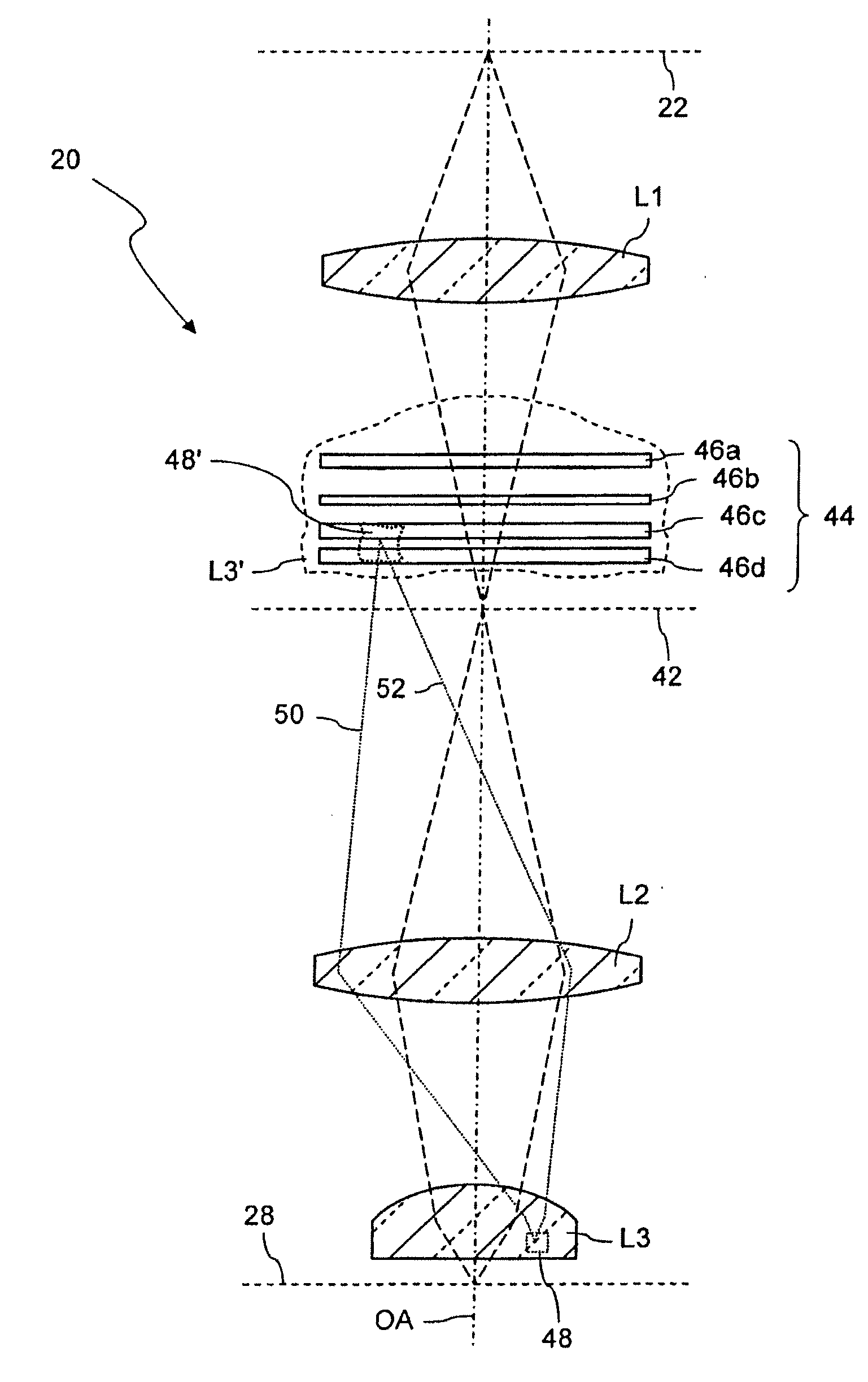
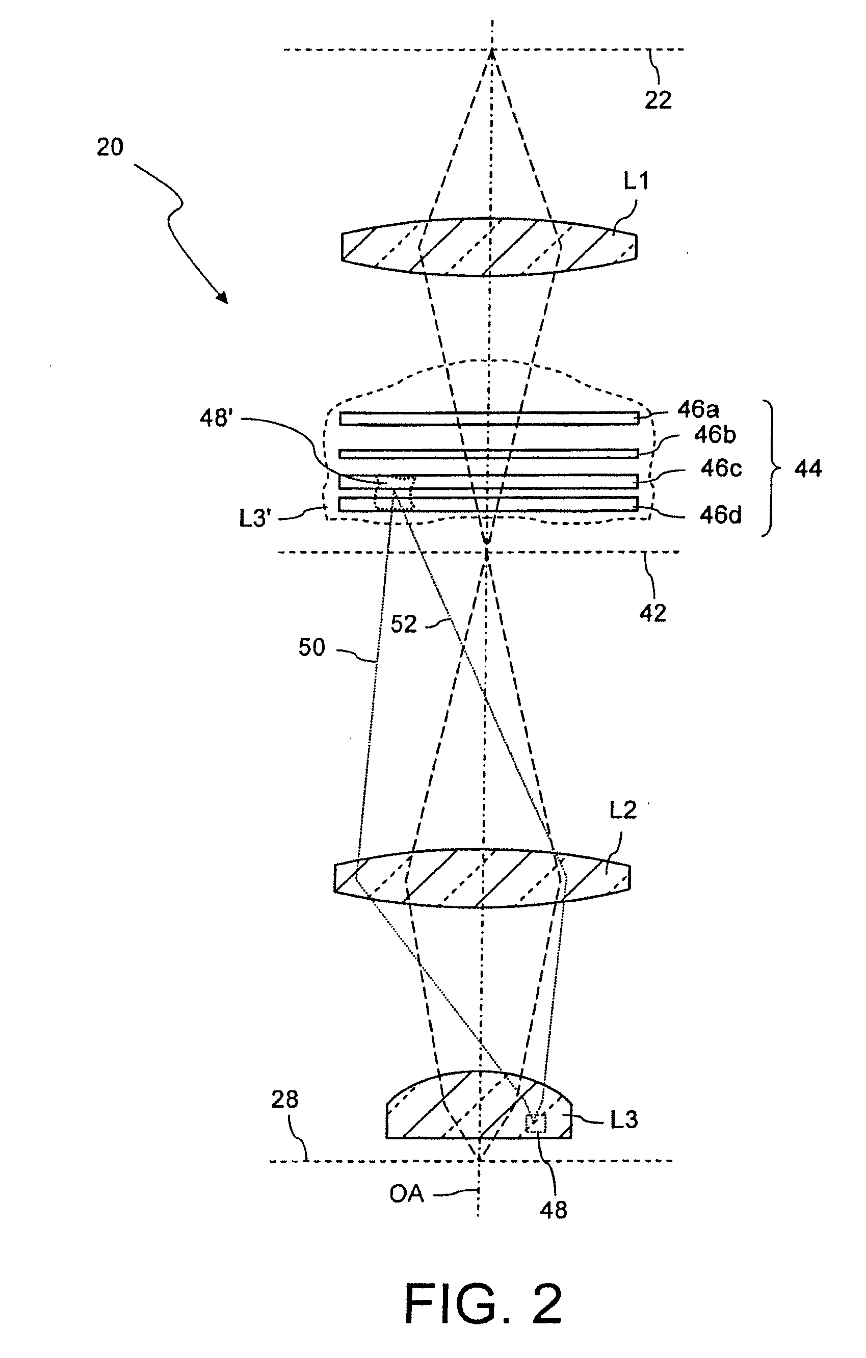
[0060]The projection exposure apparatus 10 furthermore includes a projection objective 20 which contains a plurality of optical elements such as lenses, mirrors or filter elements. For the sake of simplicity, the projection objective 20 is shown with only three lenses L1, L2 and L3; more realistic embodiments of projection objectives are shown in FIGS. 6 and 7. The projection objective 20 is used to image a mask 24, which is arranged in a mask plane 22 of the projection objective ...


PUM


Abstract

A projection objective of a microlithographic projection exposure apparatus has a high index refractive optical element (L3) with an index of refraction greater than 1.6. This element (L3) has a volume and a material related optical property which varies over the volume. Variations of this optical property cause an aberration of the objective. In one embodiment at least 4 optical surfaces are provided that are arranged in at least one volume (L3′) which is optically conjugate with the volume of the refractive optical element. Each optical surface comprises at least one correction means, for example a surface deformation or a birefringent layer with locally varying properties, which at least partially corrects the aberration caused by the variation of the optical property.

Description

CROSS-REFERENCE TO RELATED APPLICATIONS[0001]This application claims benefit of US provisional application Ser. No. 60 / 814,385 filed Jun. 16, 2006. The full disclosure of this earlier application is incorporated herein by reference.BACKGROUND OF THE INVENTION[0002]1. Field of the Invention[0003]The invention relates to a projection objective of a microlithographic projection exposure apparatus. Such apparatus are used for the production of integrated circuits and other microstructured components. In particular, the invention relates to a projection objective having a refractive optical element that has a material related optical property, e.g. the refractive index or the birefringence, which varies over the volume of the element.[0004]2. Description of the Prior Art[0005]Integrated electrical circuits and other microstructured components are conventionally produced by applying a plurality of structured layers onto a suitable substrate which, for example, may be a silicon wafer. In o...

Claims


Application Information

Patent Timeline
IPC IPC(8): G02B13/14G02B27/28G02B3/00
CPCG02B5/3091G03F7/70341G03F7/70308G02B27/0025G02B3/00G02B13/00G02B27/00G03F7/20
Inventor SCHUSTER, KARL-HEINZFELDMANN, HEIKOGRUNER, TORALFTOTZECK, MICHAELCLAUSS, WILFRIEDBEDER, SUSANNEKRAEHMER, DANIELDITTMANN, OLAF
Owner CARL ZEISS SMT GMBH
Why Eureka
Try Eureka