Read sensors and methods of making same with back-edge milling and refilling

a technology of read sensors and back-edge milling, applied in nanoinformatics, instruments, record information storage, etc., can solve the problems of introducing noise in the read signal, preventing proper magnetic performance of the mr sensor, etc., and achieve the effect of slowing down the polishing ra

Inactive Publication Date: 2009-11-19
WESTERN DIGITAL TECH INC
View PDF14 Cites 11 Cited by
  • Summary
  • Abstract
  • Description
  • Claims
  • Application Information

AI Technical Summary

Benefits of technology

[0010]According to one embodiment, a method of forming a MR read sensor includes initially milling at a first angle a portion of a MR sensor stack disposed on a first magnetic shield. Further milling the portion of the MR sensor stack at a second angle smaller than the first angle forms a back-edge of the MR sensor stack and removes part of the first magnetic shield. In addition, the method includes depositing an insulating layer on the back-edge of the MR sensor stack to partially fill a void created by the milling, and depositing a metallic non-magnetic layer on the insulating layer to complete filling of the void. The metallic non-magnetic layer provides a slower polishing rate than the insulating layer. Depositing a second magnetic shield over the MR sensor stack and the polish resistant layer completes the read sensor.

Problems solved by technology

Damage at the back-edge of the MR sensor can prevent proper magnetic performance of the MR sensor.
Further, shunting around a barrier layer of the MR sensor between the free layer and a pinned layer of the MR sensor can occur at the back edge, thereby introducing noise in the read signal.

Method used


Image

  • Read sensors and methods of making same with back-edge milling and refilling
  • Read sensors and methods of making same with back-edge milling and refilling
  • Read sensors and methods of making same with back-edge milling and refilling

Examples


Embodiment Construction

[0020]In the following, reference is made to embodiments of the invention. However, it should be understood that the invention is not limited to specific described embodiments. Instead, any combination of the following features and elements, whether related to different embodiments or not, is contemplated to implement and practice the invention. Furthermore, in various embodiments the invention provides numerous advantages over the prior art. However, although embodiments of the invention may achieve advantages over other possible solutions and / or over the prior art, whether or not a particular advantage is achieved by a given embodiment is not limiting of the invention. Thus, the following aspects, features, embodiments and advantages are merely illustrative and, unless explicitly present, are not considered elements or limitations of the appended claims.

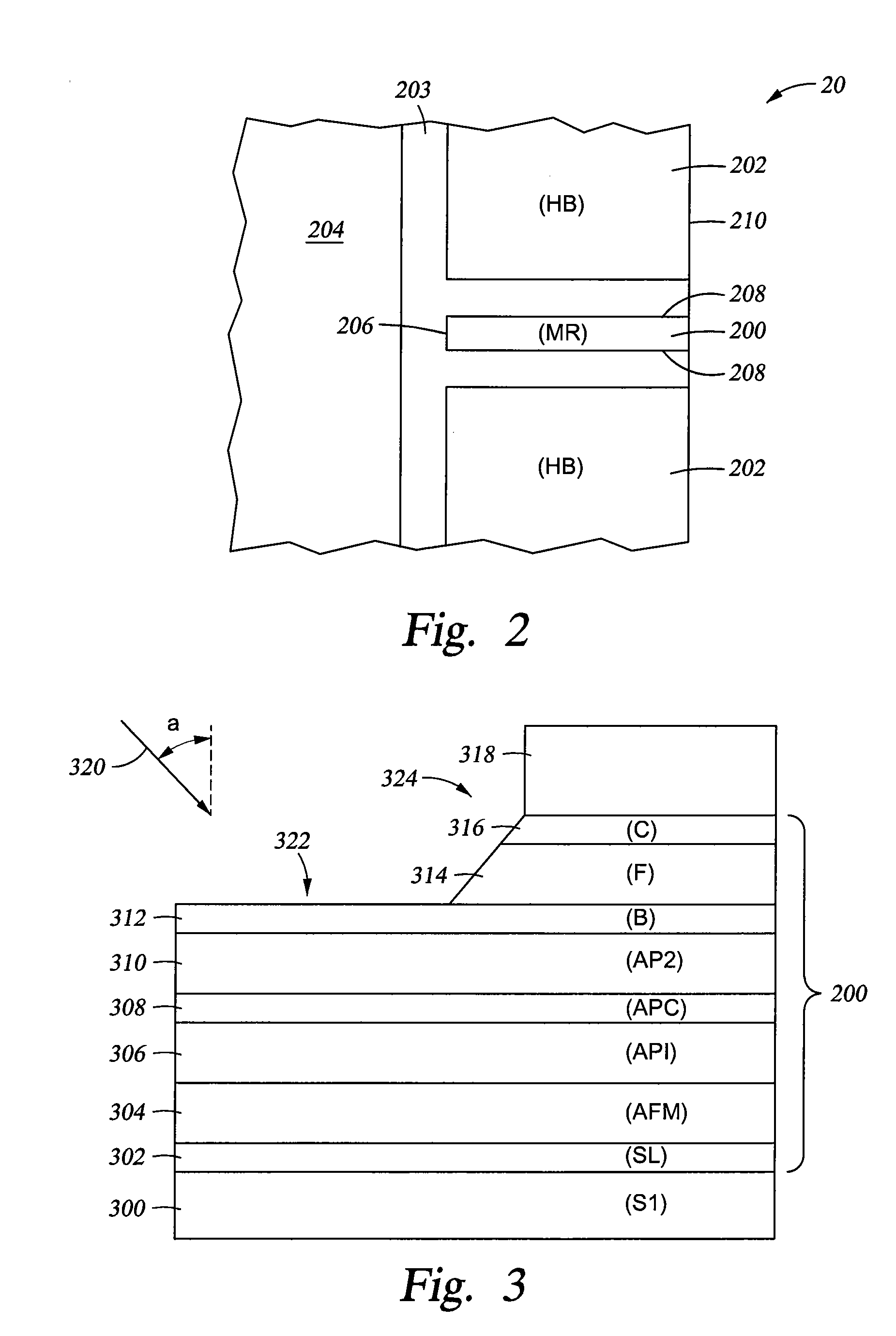
[0021]Embodiments of the invention relate to a refill configuration adjacent a back-edge that defines a height of a magnetoresist...


PUM

PropertyMeasurementUnit
angleaaaaaaaaaa
angleaaaaaaaaaa
thickaaaaaaaaaa

Abstract

Methods and apparatus provide a refill configuration adjacent a back-edge that defines a height of a magnetoresistive read sensor. Milling through layers of the sensor forms the back-edge and may be initially conducted at a first angle of incidence greater than a second angle of incidence. In combination, an insulating material and a polish resistant material, such as a non-magnetic metal, disposed on the insulating material fills a void created by the milling. The sensor further includes first and second magnetic shields with the layers of the sensor along with the polish resistant material and insulating material disposed between the first and second magnetic shields.

Description

BACKGROUND OF THE INVENTION[0001]1. Field of the Invention[0002]Embodiments of the invention generally relate to magnetoresistive reader structures for sensing data stored on magnetic media and methods of making the structures.[0003]2. Description of the Related Art[0004]In an electronic data storage and retrieval system, a magnetic head typically includes a reader portion having a magnetoresistive (MR) sensor for retrieving magnetically encoded information stored on a magnetic recording medium or disk. The MR sensor includes multiple layers and operates based on a change of resistance of the MR sensor in the presence of a magnetic field. During a read operation, a bias current is passed through the MR sensor. Magnetic flux emanating from a surface of the recording medium causes rotation of a magnetization vector of a sensing or free layer of the MR sensor, which in turn causes the change in resistance of the MR sensor. The change in resistance of the read element is detected by pas...

Claims


Application Information

Patent Timeline
Patent Type & Authority Applications(United States)
IPC IPC(8): G11B5/39B05D5/12
CPCB82Y10/00B82Y25/00G11B5/3909G11B5/3912Y10T428/1121G11B5/3163G11B5/398Y10T29/49043G11B2005/3996
Inventor GILL, HARDAYAL S.JAYASEKARA, WIPUL P.
Owner WESTERN DIGITAL TECH INC
Why Eureka
Try Eureka