
Rotary ultrasonic sealer

a rotary ultrasonic sealer and horn technology, applied in the direction of mechanical vibration separation, electrical equipment, lamination, etc., can solve the problems of increased mechanical wear between the supports and the hollow shaft, uneven operation of the rotary sealer, and large amount of energy transfer, so as to reduce the loss of energy, eliminate additional slack and tolerances, and ensure the effect of sealing

Inactive Publication Date: 2009-11-26
3L LUDVIGSEN
View PDF8 Cites 8 Cited by
  • Summary
  • Abstract
  • Description
  • Claims
  • Application Information

AI Technical Summary

Benefits of technology

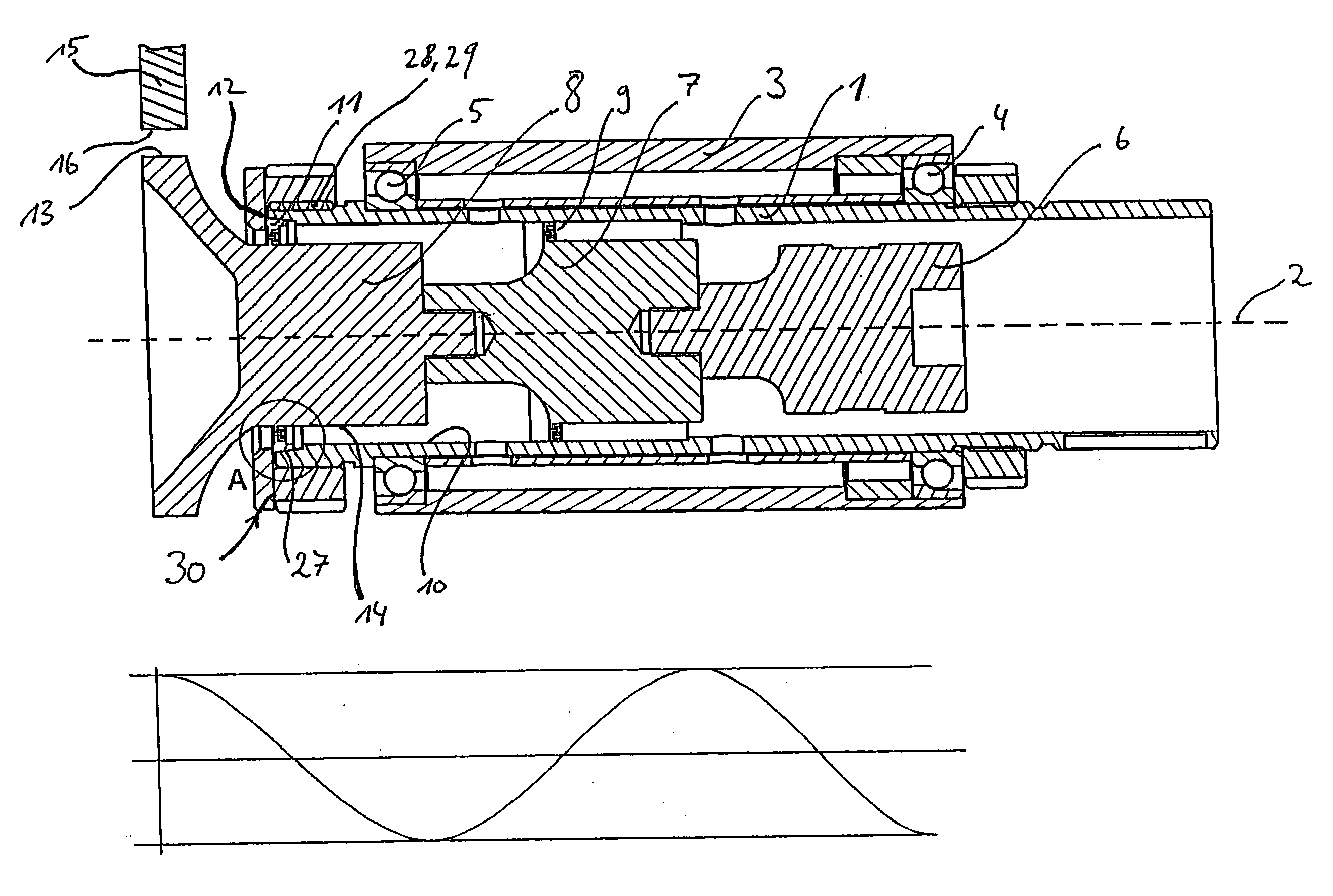
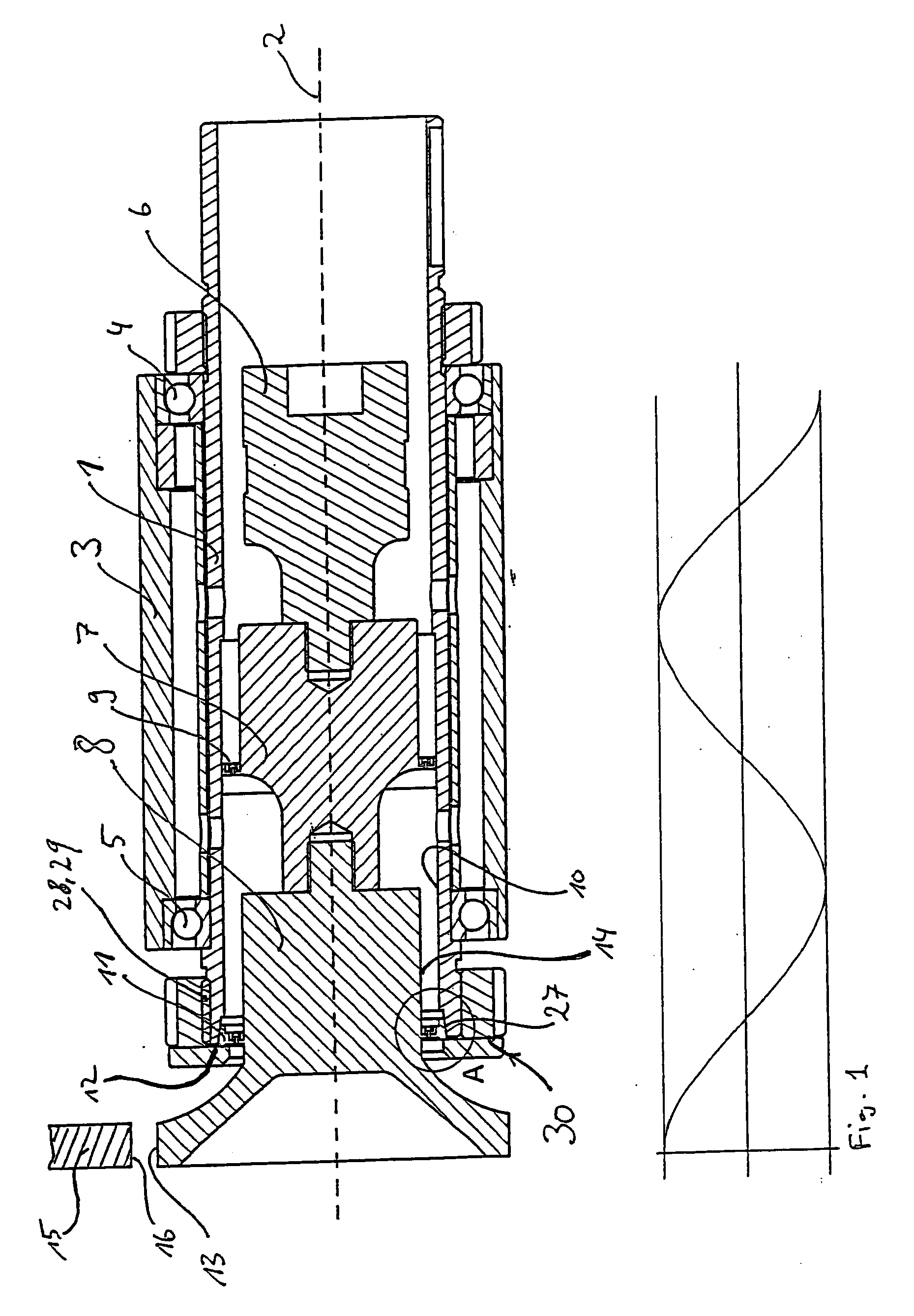
[0011]During vibration of the horn, the radial displacement or expansion of the horn is absorbed by the annular support such that substantially no vibrations are transferred to the hollow shaft and the housing, and the loss of energy is minimised or eliminated. By providing the horn with a support a very accurate positioning of the horn is furthermore obtained resulting in optimum rotation thereof with no or a minimum of slack. This is in contrast to the situation where the horn is not supported but held by the booster which in turn is supported in the hollow shaft by a support. The latter solution causes problems in particular when servicing or repairing the rotary sealer at which it is often necessary to remove the horn from the booster. When remounting the horn on the booster it is practically impossible to remount the horn in exactly the same position as before, thereby causing slack in the sealing area.
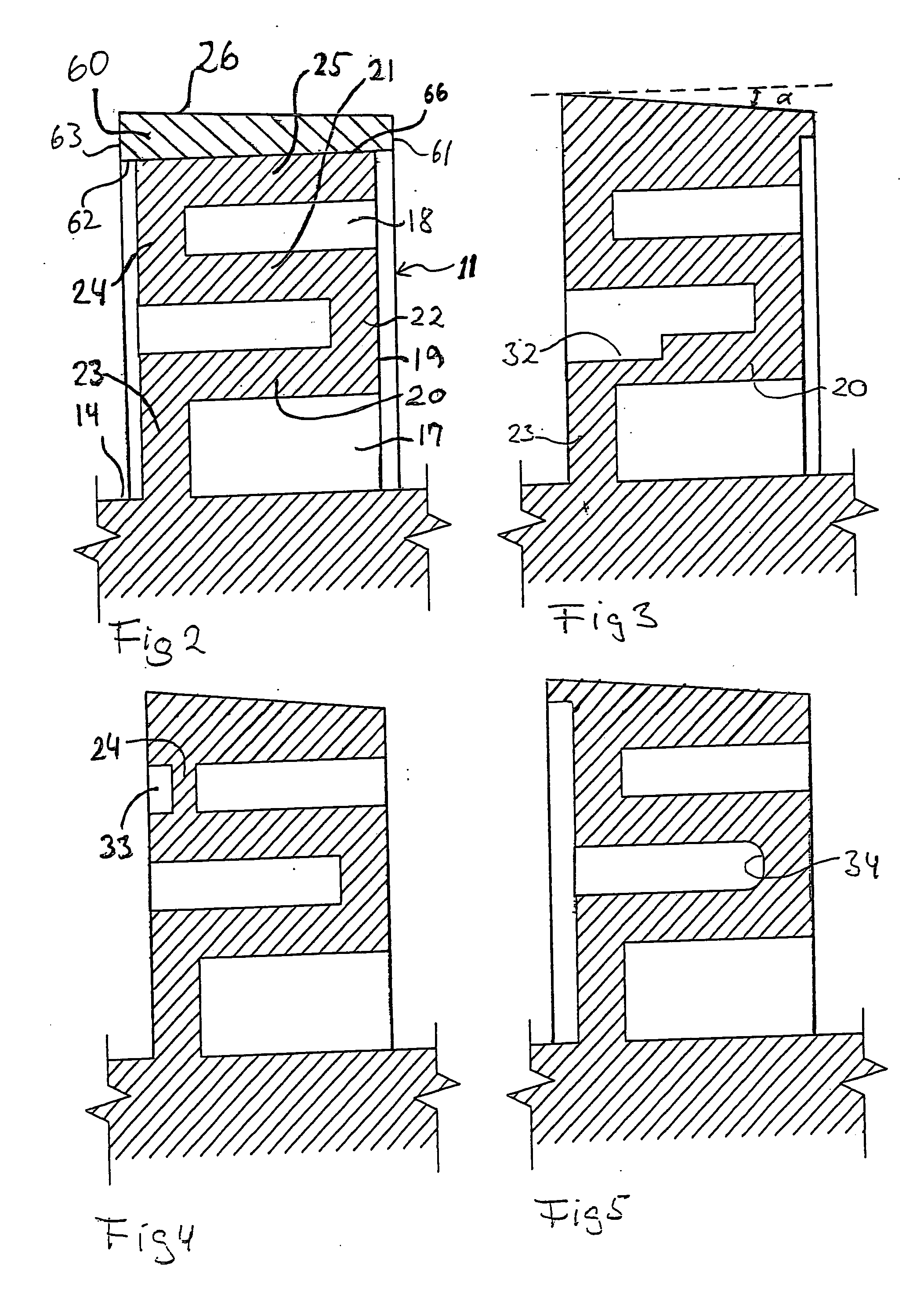
[0015]Furthermore according to the invention a radially outer part of the support is formed as a separate cone ring having a radially inner face and being press-fitted, preferably by shrinking, onto a radially outer surface of a remainder part of the support. The separate cone ring allows for producing more complex shapes of the outer surface of the remainder part of the support, the inner surface of the cone ring and / or the outer conical surface.
[0017]Moreover according to the invention the radially outer face of the remainder part of the support may be provided with a plurality of mutually interspaced recesses, whereby abutment faces are formed between the recesses, said abutment faces abutting the inner face of the cone ring. By thus reducing the abutment area between the remainder part of the support and the inner face of the cone ring, the energy loss is further reduced, i.e. the energy being transferred to the hollow shaft and from there to the housing.
[0026]In a further development of the above embodiment, an elastomeric material, such as rubber, may be arranged in the groove. The elastomeric material effects an additional dampening or absorption of the vibrations transferred to the hollow shaft and thus to the housing.
[0032]The at least one annular support is preferably arranged one quarter of a wavelength of the applied vibration from the cylindrical sealing face of the horn. The support is thereby advantageously arranged as close as possible to the sealing face of the horn and provides optimum support to the horn.

Problems solved by technology

If the supports are not suitably resilient, a large amount of energy is transferred to the hollow shaft and the housing which otherwise would be utilized in the sealing process.
Furthermore, increased mechanical wear arises between the supports and the hollow shaft, if the supports are not adequately resilient.
As a result, the rotary sealer operates unevenly with reduced precision and reduced operating life.
Additionally, an insufficiently resilient support will cause intense heating of the support areas and at worst may result in the supports being welded to the hollow shaft and / or the retaining means.
For sealing thick materials and / or sealing at high velocities, a substantial amount of energy, high amplitude and a comparatively high pressure between the sealing face of the rotating horn and the material to be sealed are required.
The high radial pressures or, when sealing at high velocities, centrifugal forces acting on the slightest imbalance in the horn will result in a bending of the horn assembly.
Known rotary sealers do not allow for sealing under the above operating conditions without compromising the required precision and without large amounts of energy being dissipated in the hollow shaft and the housing resulting in energy loss and a risk of welding the support to the hollow shaft.

Method used


Image

  • Rotary ultrasonic sealer
  • Rotary ultrasonic sealer
  • Rotary ultrasonic sealer

Examples


Embodiment Construction

[0009]The object of the invention is thus to provide a rotary sealer of the above type remedying the above drawbacks of prior art.

[0010]The rotary sealer according to the invention is characterised in that the support at its periphery comprises a conical surface having a proximal end and a distal end, which conical surface is adapted to cooperate with a corresponding conical surface for centring the support with respect to the hollow shaft when the horn is retained in the hollow shaft by means of the retaining means.

[0011]During vibration of the horn, the radial displacement or expansion of the horn is absorbed by the annular support such that substantially no vibrations are transferred to the hollow shaft and the housing, and the loss of energy is minimised or eliminated. By providing the horn with a support a very accurate positioning of the horn is furthermore obtained resulting in optimum rotation thereof with no or a minimum of slack. This is in contrast to the situation where ...


PUM

PropertyMeasurementUnit
Widthaaaaaaaaaa
Areaaaaaaaaaaa
Circumferenceaaaaaaaaaa

Abstract

Horn assembly adapted to be rotatably arranged in a housing (3) of a rotary ultrasonic sealer, and comprising a hollow shaft (1) having a longitudinal axis (2) and a horn (8) arranged coaxially in the hollow shaft (1) and connected to a converter (6) and preferably also a booster (7). The horn (8) is provided with a peripheral sealing area (13) outside an axial end (13) of the hollow shaft (1). The horn (8) is connected to the hollow shaft (1) by means of at least one annular, metallic support (11) extending radially outward from an outer face (14) of the horn (8) and axially acting retaining means so as to fixedly retain the horn (8) in the hollow shaft (1). The at least one annular support (11) is corrugated in cross section such that at least two grooves and one ridge arranged there between are provided between the inner face (10) of the hollow shaft (1) and the outer face (14) of the horn (8). The at least one support (11) comprises at its outer circumference a conical surface (26) adapted to cooperate with a corresponding conical surface (27) for centring the support (11) with respect to the hollow shaft (1).

Description

TECHNICAL FIELD[0001]The invention relates to a horn assembly adapted to be rotatably arranged in a housing of a rotary ultrasonic sealer, and comprising a hollow shaft having a longitudinal axis and a horn arranged coaxially in the hollow shaft and connected to a converter and preferably also a booster, the horn being provided with a peripheral sealing area outside an axially free end of the hollow shaft and the housing, and wherein the horn is connected to the hollow shaft by means of at least one annular, metallic support extending radially outward from an outer face of the horn and retaining means so as to fixedly retain the horn in the hollow shaft, said support being arranged essentially in a point with minimum vibration amplitude in the longitudinal direction of the horn, wherein the at least one annular support is corrugated in cross section such that at least two grooves and one ridge arranged there between are provided between the inner face of the hollow shaft and the out...

Claims


Application Information

Patent Timeline
IPC IPC(8): B06B3/00
CPCB06B3/00B29C65/085B29C66/83411B29C66/83413Y10T156/1741B29C65/081B29C65/087B29C65/088B29C66/83417
Inventor VOSS, BRIAN
Owner 3L LUDVIGSEN
Learn More