Magnetic Induction Device

a magnetic induction device and inductance technology, applied in the direction of transformer/react mounting/support/suspension, instruments, etc., can solve the problems of imbalance, ineffectiveness of conventional transformers, complex magnetic devices and designs, etc., to reduce leakage inductance, reduce metallic losses, and enhance common-mode (cm) signal rejection

Inactive Publication Date: 2009-11-26
ADVANCED MAGNETIC SOLUTIONS
View PDF5 Cites 13 Cited by
  • Summary
  • Abstract
  • Description
  • Claims
  • Application Information

AI Technical Summary

Benefits of technology

[0042]Yet further in accordance with a preferred embodiment of the present invention there is provided a method of reducing leakage inductance and enhancing common-mode (CM) signal rejection in a magnetic induction device, the method including providing at least one primary electrical winding, and at least one secondary electrical winding, at least partially surrounding a core via which the at least one primary electrical winding and the at least one secondary electrical winding are magnetically coupled, by an electrically-conductive cover (ECC) without forming a closed conductive loop, and electrically connecting the ECC to a local ground.
[0043]There is also provided in accordance with a preferred embodiment of the present invention a method of reducing metallic losses in a magnetic induction device, the method including providing a ribbon cable, electrically connecting each wire in the ribbon cable, at at least one location, to adjacent wires in the ribbon cable so as to produce a conductive path throughout all wires in the ribbon cable, and wrapping the ribbon cable around a core of a magnetic induction device so as to produce an electrical winding of the magnetic induction device.
[0044]Further in accordance with a preferred embodiment of the present invention there is provided a method for reducing leakage inductance in an inductor, the method including at least partially surrounding a core by an electrically-conductive cover (ECC) without forming a closed conductive loop, and winding an electrical winding on the ECC.

Problems solved by technology

Conventional transformers, when used with balanced signals, are typically not sufficiently effective in rejecting common-mode (CM) currents in a frequency band above several hundreds of MHz.
Ineffectiveness of the conventional signal transformers in rejecting CM currents resulted till now in complex magnetics devices and designs being used in order to obtain a solution for communication applications.
Complexity of magnetics design led to imbalance problems, which in turn are a source of electromagnetic interference (EMI) problems and crosstalk.
Some aspects of technologies and related material that deal with reduction of interwinding capacitance in isolation transformers and result in some enhancement of common-mode rejection but do not address the problem of controlling leakage inductance are described in the following publications:

Method used


Image

  • Magnetic Induction Device
  • Magnetic Induction Device
  • Magnetic Induction Device

Examples


Embodiment Construction

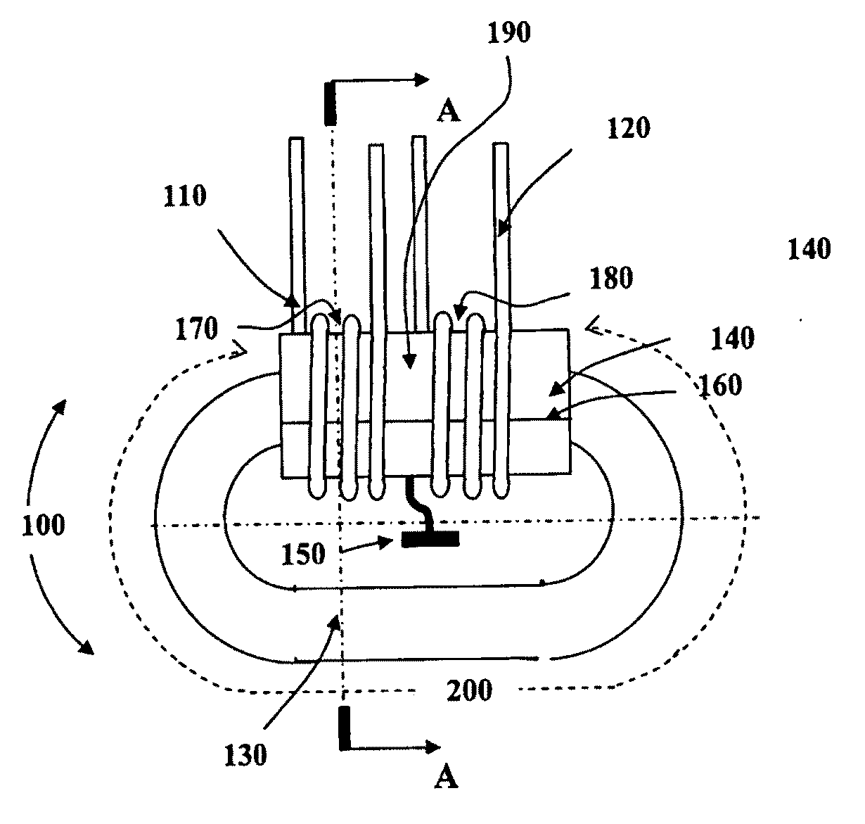
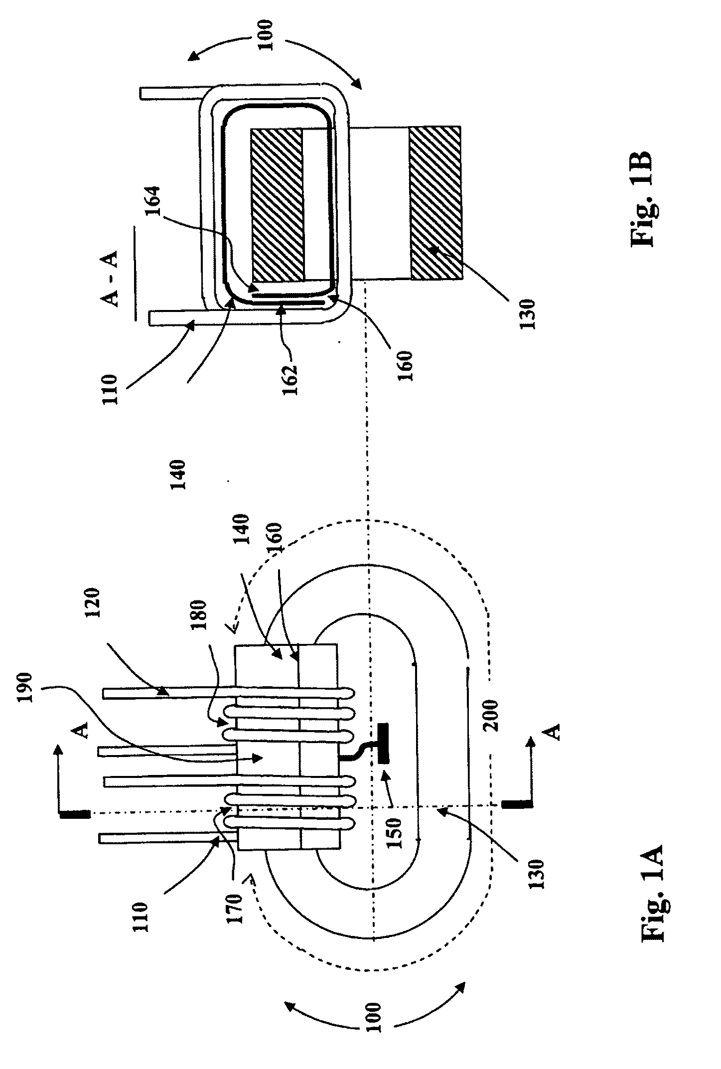
[0064]Reference is now made to FIG. 1A, which is a simplified pictorial illustration of a preferred implementation of a magnetic induction device (MID) 100 comprising a transformer which employs a grounded Electrically-Conductive Cover (ECC), the MID 100 being constructed and operative in accordance with a preferred embodiment of the present invention.

[0065]The MID 100 may, for example which is not meant to be limiting, be used as a transformer in various applications including, for example, communication applications. The MID 100 preferably includes the following elements: at least one primary electrical winding 110; at least one secondary electrical winding 120; a core 130 via which the at least one primary electrical winding 110 and the at least one secondary electrical winding 120 are magnetically coupled; and an ECC 140. For simplicity of description and depiction, only one primary electrical winding 110 and one secondary electrical winding 120 are shown in FIG. 1A and referred...


PUM

PropertyMeasurementUnit
frequenciesaaaaaaaaaa

Abstract

A magnetic induction device (MID) is described. The MID comprises at least one primary electrical winding, at least one secondary electrical winding, and an electrically-conductive cover (BCC) which is electrically connected to a local ground and at least partially surrounds, without forming a closed conductive loop, a core via which the at least one primary electrical winding and the at least one secondary electrical winding are magnetically coupled. Related apparatus and methods are also described.

Description

FIELD OF THE INVENTION[0001]The present invention generally relates to magnetic induction devices and to circuitries that use magnetic induction devices.BACKGROUND OF THE INVENTION[0002]Magnetic induction devices, such as transformers and Baluns (Balun—Balanced-Unbalanced), are typically used in various systems, such as in communication systems. Conventional transformers, when used with balanced signals, are typically not sufficiently effective in rejecting common-mode (CM) currents in a frequency band above several hundreds of MHz. Sufficiently high CM rejection is especially important at high-speed data communication applications for prevention of conducted and radiated emissions, and for enhancement of data interface noise immunity.[0003]Ineffectiveness of the conventional signal transformers in rejecting CM currents resulted till now in complex magnetics devices and designs being used in order to obtain a solution for communication applications. Such complex devices and designs ...

Claims


Application Information

Patent Timeline
Patent Type & Authority Applications(United States)
IPC IPC(8): H01F27/36H01F27/28
CPCH01F17/062H01F2017/0093H01F27/367H01F27/36H01F27/363H01F27/06H01F7/06G11B5/127
Inventor SHPIRO, ZEEVAXELROD, ALEX
Owner ADVANCED MAGNETIC SOLUTIONS
Why Eureka
Try Eureka