RFID system

a technology of rfid system and rfid antenna, which is applied in the direction of resonant antenna, burglar alarm mechanical actuation, instruments, etc., can solve the problems of insufficient resolution of current rfid system, inability to provide the resolution necessary to achieve satisfactory, and comparatively limited number of products

Active Publication Date: 2009-11-26
DEKA PROD LLP
View PDF17 Cites 184 Cited by
  • Summary
  • Abstract
  • Description
  • Claims
  • Application Information

AI Technical Summary

Benefits of technology

[0018]In another implementation, an RFID antenna assembly is configured to be energized with a carrier signal. The RFID antenna assembly includes an inductive component having a multi-segment loop antenna assembly. The multi-segment loop antenna assembly includes at least a first antenna segment having at least a first phase shift element configured to reduce the phase shift of the carrier signal within the at least a first antenna segment. At least a second antenna segment includes at least a second phase shift element configured to reduce the phase shift of the carrier signal within the at least a second antenna segment. The RFID antenna assembly includes at least one far field antenna assembly. The length of each antenna segment is no more than 25% of the wavelength of the carrier signal. At least one matching component is configured to adjust the impedance of the multi-segment loop antenna assembly.
[0019]One or more of the following features may be included. The inductive component may be configured to be positioned proximate an access assembly of a processing system and to allow RFID-based actuation of the access assembly. The far field antenna assembly may be a dipole antenna assembly. The far field antenna assembly may include a first antenna portion and a second antenna portion. The sum length of the first antenna portion and the second antenna portion may be greater than 25% of the wavelength of the carrier signal.
[0020]The details of one or more implementations are set forth in the accompanying drawings and the description below. Other features and advantages will become apparent from the description, the drawings and the claims.

Problems solved by technology

Unfortunately, such systems are often static in configuration and are only capable of generating a comparatively limited number of products.
While such systems may be capable of being reconfigured to generate other products, such reconfiguration may require extensive changes to mechanical / electrical / software systems.
Unfortunately, due to the advancing complexity of such processing systems, current RFID systems may not provide the resolution necessary to achieve satisfactory results.

Method used


Image

  • RFID system
  • RFID system
  • RFID system

Examples


Embodiment Construction

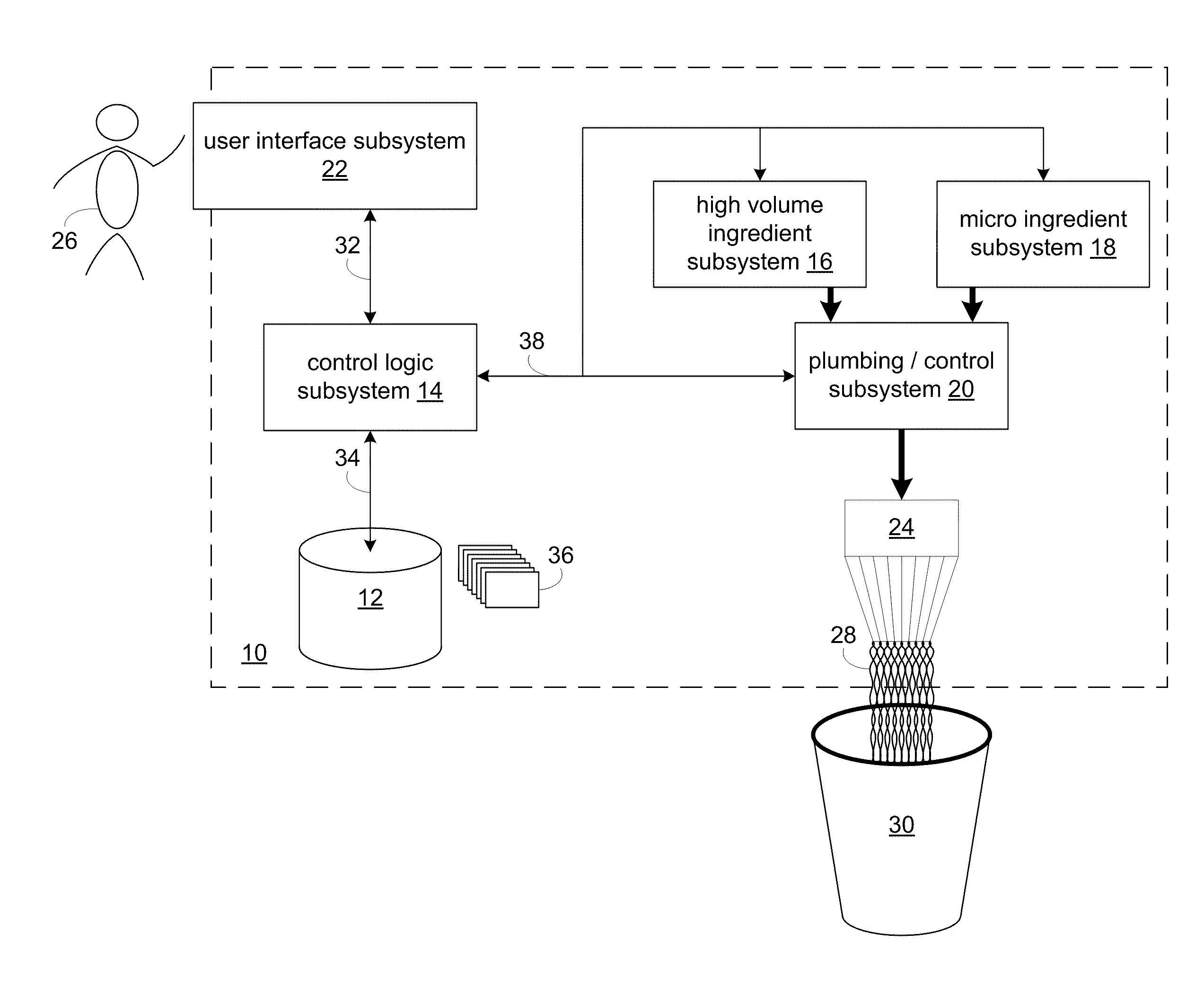
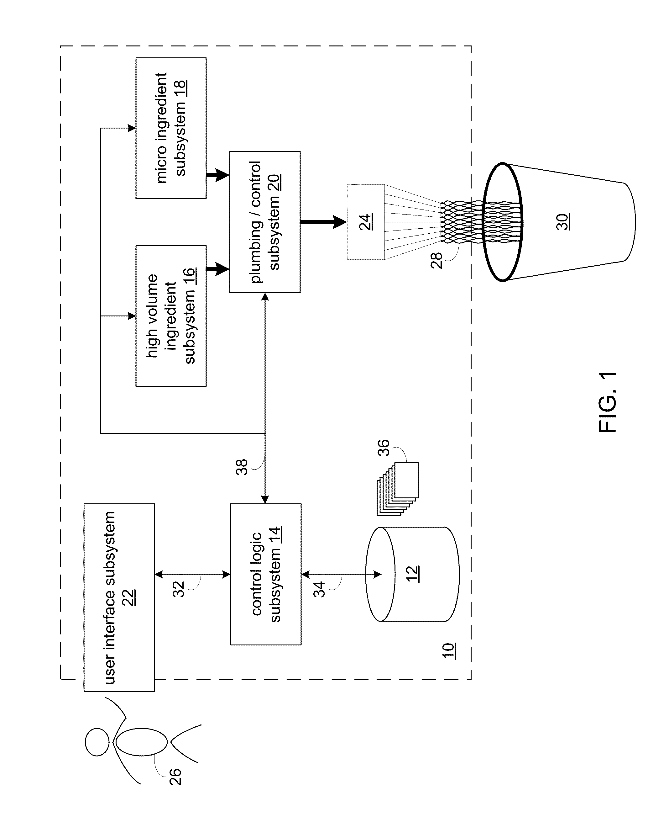
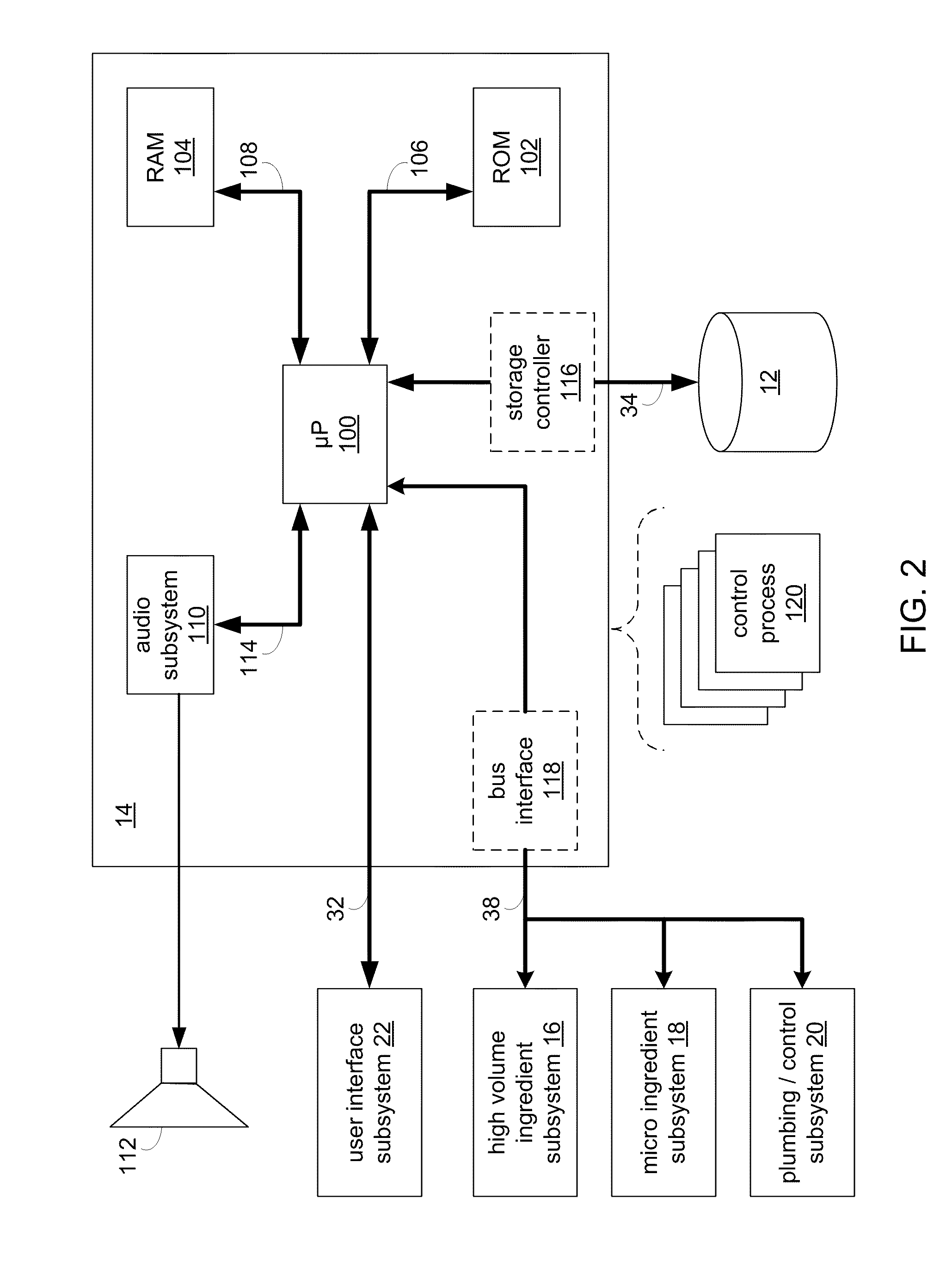
[0045]Described herein are various RFID (i.e., Radio Frequency Identification) systems that may be utilized to wirelessly identify various objects. RFID systems typically include an RFID reader that allows for the reading of RFID tags. The RFID tags may be attached to / associated with various objects and may include electronically encoded information that specifically identifies the object to which the RFID tag is attached / associated. For example, an RFID tag may be attached to the windshield of a car and may be used to gain wireless access to a parking garage. Further, an RFID tag may be carried in a wallet / purse and allow wireless access to an office building. Additionally, an RFID tag may be implanted into a family pet so that, in the event that the pet is lost, the ownership information encoded within the tag may be wirelessly read and the pet returned to their owner. Further still, RFID tags may be used within product dispensing systems so that various ingredient / chemical / produc...


PUM


Abstract

A magnetic field focusing assembly includes a magnetic field generating device configured to generate a magnetic field, and a split ring resonator assembly configured to be magnetically coupled to the magnetic field generating device and configured to focus the magnetic field produced by the magnetic field generating device.

Description

RELATED APPLICATION(S)[0001]This application claims the benefit of U.S. provisional patent application Ser. No. 61 / 054,757, filed 20 May 2008, and entitled RFID SYSTEM AND METHOD; and U.S. provisional patent application Ser. No. 61 / 168,364, filed 10 Apr. 2009, and entitled SYSTEMS, DEVICES, AND METHODS FOR COMMUNICATION USING SPLIT RING RESONATORS; wherein the entire disclosure of each application is incorporated herein by reference.TECHNICAL FIELD[0002]This disclosure relates to RFID systems and, more particularly, to RFID systems that generate focused magnetic fields.BACKGROUND[0003]Processing systems may automate the combination of one or more substrates to form a product. Unfortunately, such systems are often static in configuration and are only capable of generating a comparatively limited number of products. While such systems may be capable of being reconfigured to generate other products, such reconfiguration may require extensive changes to mechanical / electrical / software sy...

Claims


Application Information

Patent Timeline
Patent Type & Authority Applications(United States)
IPC IPC(8): G08B13/14H01P7/00H01Q1/50
CPCH01Q1/2225H01Q7/005H01Q7/00H01Q1/2208H01Q1/50H01Q9/16
Inventor BLUMBERG, JR., DAVID
Owner DEKA PROD LLP
Why Eureka
Try Eureka