Laser microscope

a laser microscope and microscope technology, applied in the field of laser microscopes, can solve the problems of large system, complicated mechanism, and use of even larger system, and achieve the effect of high-precision observation and simple configuration

Inactive Publication Date: 2009-11-26
EVIDENT CORP
View PDF4 Cites 10 Cited by
  • Summary
  • Abstract
  • Description
  • Claims
  • Application Information

AI Technical Summary

Benefits of technology

[0027]By doing so, the variation in beam diameter and beam divergence angle, which vary when compensating the group-velocity-delay dispersion with the grating, can be reduced by the beam-shaping optical system, and therefore, adjustment is possible so that the ultrasho...

Problems solved by technology

Therefore, the system becomes large, and a complicated mechanism is required for shifting the prisms and mirrors in ...

Method used


Image

  • Laser microscope
  • Laser microscope
  • Laser microscope

Examples


first embodiment

[0032]A laser microscope 1 according to the present invention will be described below with reference to FIGS. 1 and 2.

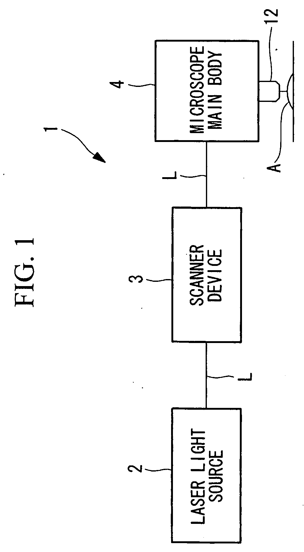
[0033]As shown in FIG. 1, the laser microscope 1 according to this embodiment includes a laser light source (light source) 2 that generates femtosecond-pulse laser light (ultrashort-pulse laser light) L, a scanner device 3 that scans the femtosecond-pulse laser light L emitted from the laser light source 2, and a microscope main body 4 that irradiates a specimen A with the femtosecond-pulse laser light L scanned by the scanner device 3 and detects fluorescence.

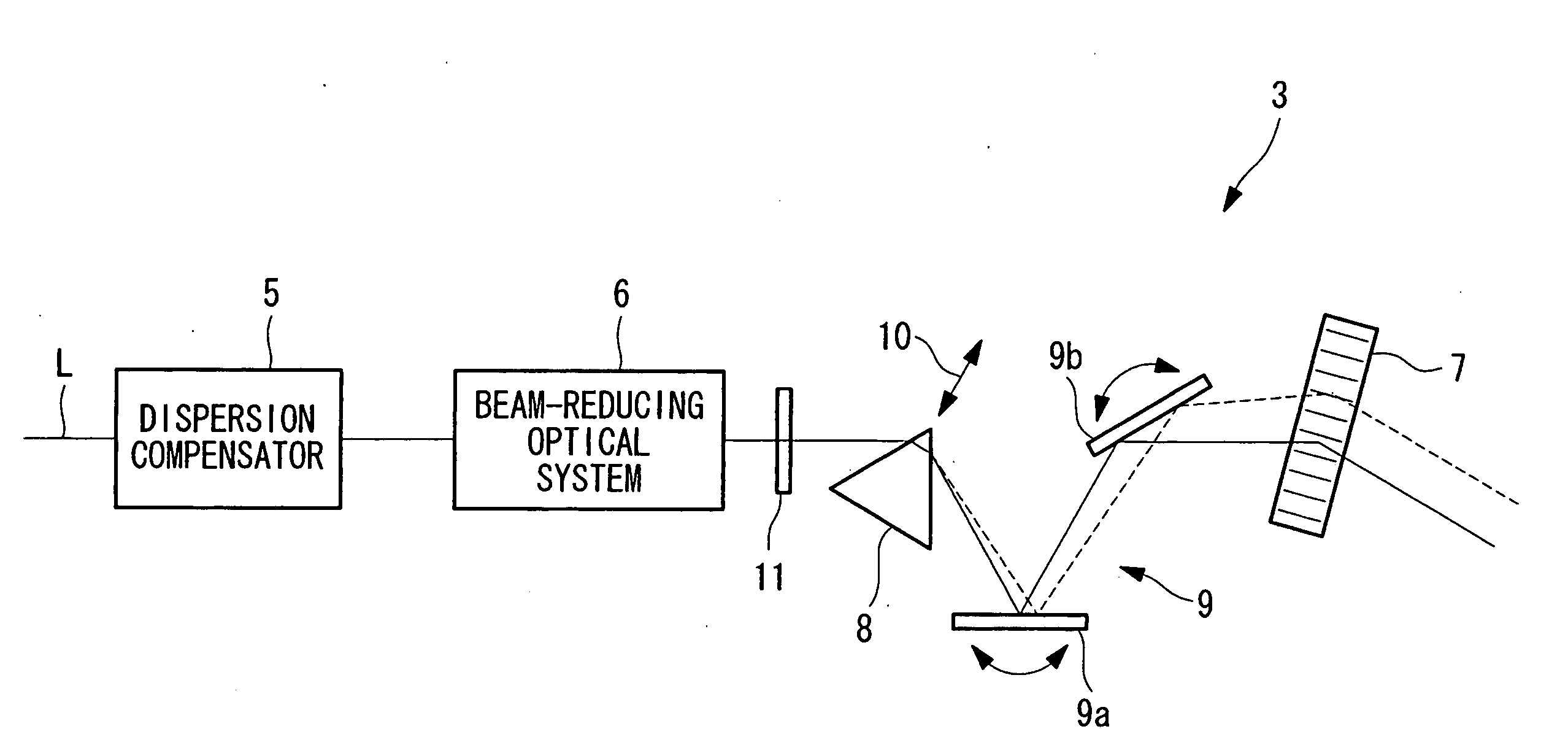
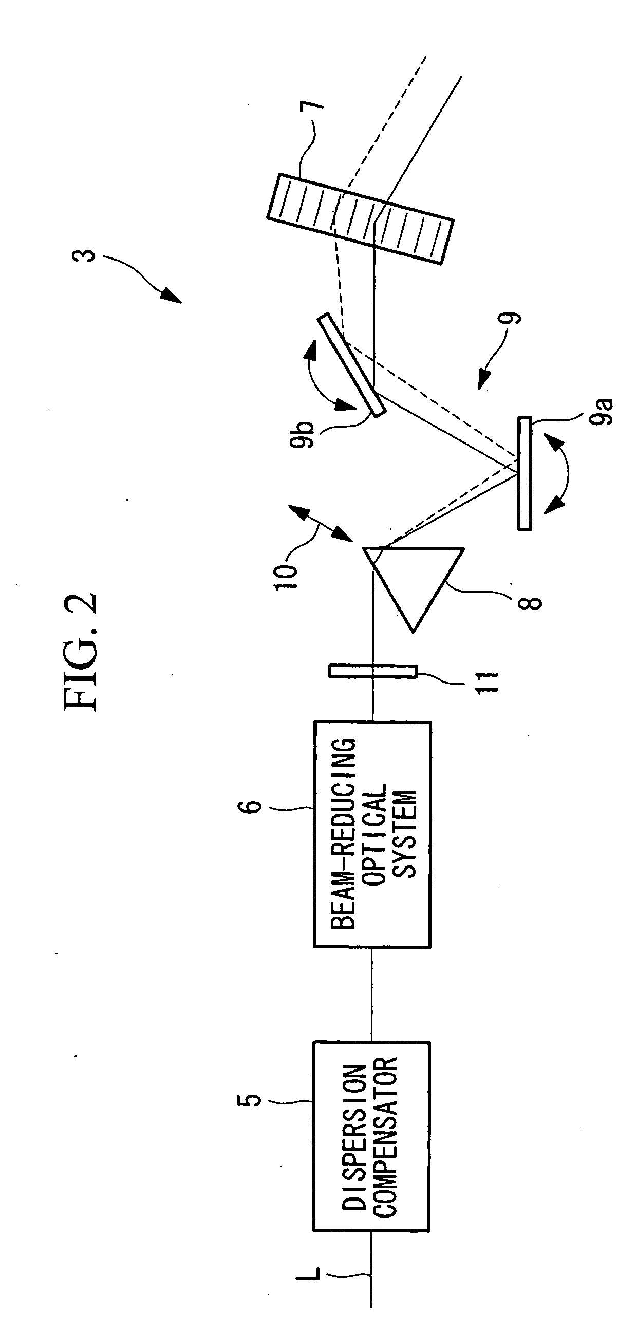
[0034]As shown in FIG. 2, the scanner device 3 includes a dispersion compensator 5 that roughly compensates the group-velocity-delay dispersion generated in the light paths of the femtosecond-pulse laser light L emitted from the laser light source 2 in the entire laser microscope 1, a beam-reducing optical system (beam-shaping optical system) 6 that adjusts the beam diameter of the femtosecond-pulse laser light...

second embodiment

[0056]Next, a laser microscope according to the present invention will be described below with reference to FIG. 3.

[0057]In the description of this embodiment, parts having the same configuration as those in the laser microscope according to the first embodiment described above are assigned the same reference numerals, and a description thereof will be omitted.

[0058]As shown in FIG. 3, the laser microscope 1 according to this embodiment includes a dispersion-compensating optical system 18, composed of static mirrors 15 and 16 and a reflection grating (angular-dispersion element) 17, and a variable-magnification beam-reducing optical system (beam-shaping optical system) 19, which are disposed between the laser light source 2 (see FIG. 1) and the acousto-optic deflector 7.

[0059]The dispersion-compensating optical system 18 is configured to move a slider (group-velocity-delay dispersion-amount adjusting unit) 20, on which the static mirror 15 and the movable grating 17 are mounted, in ...


PUM


Abstract

It is an object to perform high-precision observation by compensating group-velocity-delay dispersion and angular dispersion with a simple structure. The invention provides a laser microscope 1 including a light source; an acousto-optic deflector 7 that deflects ultrashort-pulse laser light L emitted from the light source; an angular-dispersion element 8, disposed in front of or after the acousto-optic deflector 7, that applies angular dispersion in a direction opposite to the acousto-optic deflector 7; and a group-velocity-delay dispersion-amount adjusting unit 10 that adjusts the amount of dispersion compensation by moving the angular-dispersion element 8 so as to vary the optical path length at each wavelength between the angular-dispersion element 7 and the acousto-optic deflector 8.

Description

BACKGROUND OF THE INVENTION[0001]1. Field of the Invention[0002]The present invention relates to a laser microscope.[0003]This application is based on Japanese Patent Application No. 2008-136979, the content of which is incorporated herein by reference.[0004]2. Description of Related Art[0005]A known laser microscope in the related art is provided with an acousto-optic deflector that can perform even random scanning at high speed compared with a galvanometer mirror, without any mechanical parts (for example, see U.S. Patent Application, Publication No. 2002 / 0149769). In this laser microscope, an angular-dispersion element formed of a prism is inserted before or after the acousto-optic deflector to compensate for angular dispersion of the acousto-optic deflector.[0006]Since the acousto-optic deflector is an optical element having large group-velocity-delay dispersion, and therefore, this dispersion must be compensated for. One known technique of compensating for the group-velocity-de...

Claims


Application Information

Patent Timeline
IPC IPC(8): G02F1/33
CPCG02B21/0036
Inventor KUBO, HIROKAZU
Owner EVIDENT CORP
Why Eureka
Try Eureka