Fuel cell system

a fuel cell and system technology, applied in the field of fuel cell systems, can solve the problems of noise and vibration in fuel cell vehicles, and achieve the effect of accelerating the warm-up operation of the battery

Active Publication Date: 2009-11-26
HONDA MOTOR CO LTD
View PDF3 Cites 5 Cited by
  • Summary
  • Abstract
  • Description
  • Claims
  • Application Information

AI Technical Summary

Benefits of technology

[0018]According to the above described fuel cell system, when the command rotational speed within the first rotational speed region is calculated, if the battery is in the warm-up operation, because the compressor controlling means changes the first SOC to the third SOC which is less than the first SOC, it becomes easy to change the command rotational speed of the compressor to the rotational speed within the second rotational speed region. Along with the above, the battery controlled by the battery controlling means becomes likely to discharge. And, as the battery discharges, self heat generation associated with the discharge is increased, and the warm-up operation of the battery can be accelerated.

Problems solved by technology

Such noise and vibration are noticeable in a fuel cell vehicle, etc. on which an engine is not mounted.

Method used


Image

  • Fuel cell system
  • Fuel cell system
  • Fuel cell system

Examples


Embodiment Construction

[0030]Referring to FIGS. 1-5, one embodiment of the present invention will be explained.

>

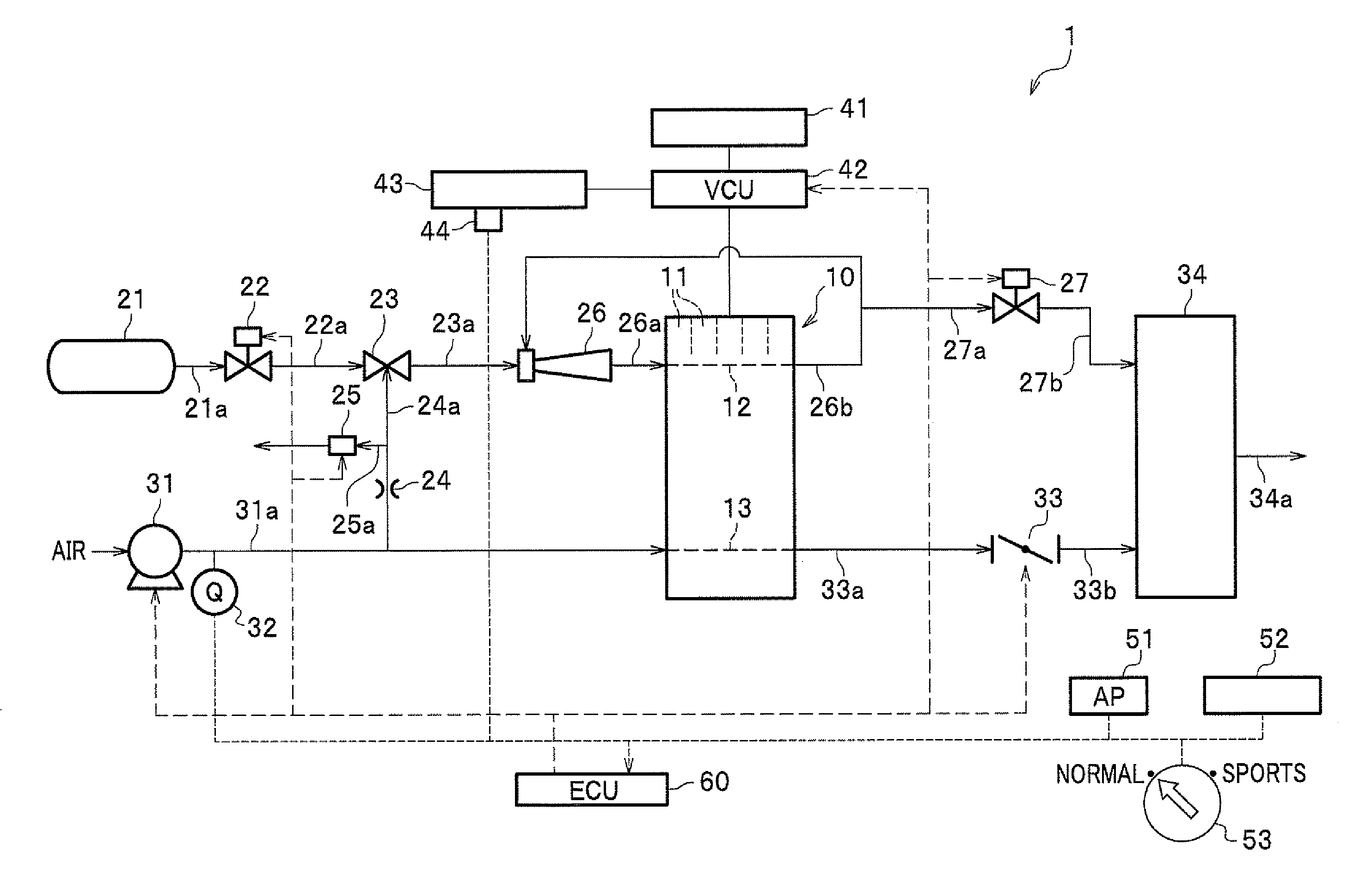
[0031]A fuel cell system 1 of this embodiment shown in FIG. 1 is mounted on a fuel cell vehicle (not shown). The fuel cell system 1 includes a fuel cell stack 10; an anode system (fuel gas supplying means) for supplying / exhausting a hydrogen (fuel gas, reaction gas) to / from an anode of the fuel cell stack 10; a cathode system for supplying / exhausting an oxygen-containing air (oxidant gas, reaction gas) to / from a cathode of the fuel cell stack 10; an electric power consuming system for consuming an electric power generated by the fuel cell stack 10; an accelerator pedal (AP) 51; and an electronic control unit (ECU) 60.

[0032]The fuel cell stack 10 is made by stacking a plurality of polymer electrolyte type single cells 11 (e.g., 200-400 cells). The plurality of single cells 11 are electrically connected in series. The single cell 11 includes a membrane electrode assembly (MEA) sandwiched between a...


PUM

PropertyMeasurementUnit
rotational speedaaaaaaaaaa
power generationaaaaaaaaaa
electric poweraaaaaaaaaa

Abstract

An object of the present invention is to provide a fuel cell system in which a noise and a vibration of a compressor can be suppressed. In order to achieve the above object, the present invention provides a fuel cell system including a fuel cell; a compressor for supplying an oxidant gas to the fuel cell, having a first rotational speed region within which as a rotational speed increases, a noise becomes greater than a predetermined value, and a second rotational speed region within which as the rotational speed increases, the noise becomes equal to or less than the predetermined value; and a compressor controller for controlling the compressor by calculating a command rotational speed for commanding the compressor based on a required amount of power generation.

Description

CROSS REFERENCE TO RELATED APPLICATIONS[0001]The present application claims benefit of the filing date of Japanese Patent Application No. 2008-133615 filed on May 21, 2008 which is incorporated herein by reference.FIELD OF THE INVENTION[0002]The present invention relates to a fuel cell system.DESCRIPTION OF THE RELATED ART[0003]Recently, studies have been widely made to develop a fuel cell, such as a polymer electrolyte fuel cell (PEFC), in which an electric power is generated by using a hydrogen (fuel gas, reaction gas) supplied to an anode and an oxygen-containing air (oxidant gas, reaction gas) supplied to a cathode.[0004]Usually, such air is supplied from a compressor, and a rotational speed (rpm) of the compressor is controlled based on a required amount of power generation for a fuel cell. That is, the required amount of power generation for the fuel cell is proportional to the rotational speed of the compressor. Therefore, when the required amount of power generation is incre...

Claims


Application Information

Patent Timeline
Patent Type & Authority Applications(United States)
IPC IPC(8): H01M8/04
CPCH01M8/04089H01M16/006Y02T90/32Y02E60/50H01M2250/20Y02E60/10Y02T90/40
Inventor MIYATA, KOICHIROAOYAGI, SATOSHIUEDA, KENICHIROUEHARA, JUNJISHIRASAKA, TAKUYAMATSUMOTO, YUJI
Owner HONDA MOTOR CO LTD
Why Eureka
Try Eureka