Flame structure of gas burner

Inactive Publication Date: 2009-11-26
KYUNGDONG NAVIEN
View PDF39 Cites 16 Cited by
  • Summary
  • Abstract
  • Description
  • Claims
  • Application Information

AI Technical Summary

Benefits of technology

[0011]Thanks to the features of the present invention, due to the fact that impingement injection of flame between adjoining fire hole pieces is made possible through the fire holes, which are defined in at least two directions inclined relative to a vertical direction, a flame holding characteristic can be improved, and excellent flame stability can be maintained even in combustion under a high load. Also, because the vertical length of the flame is decreased, incomplete combustion due to contact between the heat exchanger and flame can be prevented, the size of the burner can be reduced, and the combustion load can be increased.
[0012]Moreove

Problems solved by technology

The conventional fire hole part structure has problems in that the combustion surface thereof is likely to be distorted or the shape of the fire holes is likely to be changed due to deformation by thermal stress, whereby incomplete combustion or backfiring can be caused.
However, this structure incurs substantial material costs, and the manufacturing procedure is complicated, so that the manufacturing costs are increased.
Also, because the configuration of a premixer is complex, pressure loss increases, the flame is unstable, and noise occ

Method used


Image

  • Flame structure of gas burner
  • Flame structure of gas burner
  • Flame structure of gas burner

Examples


Example

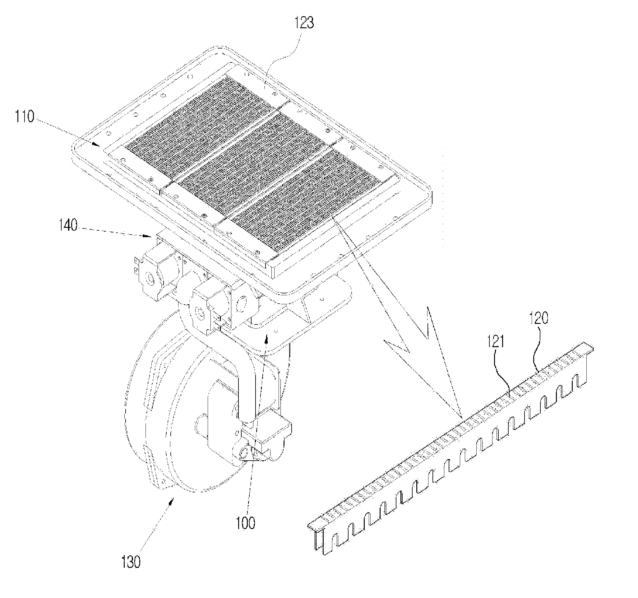
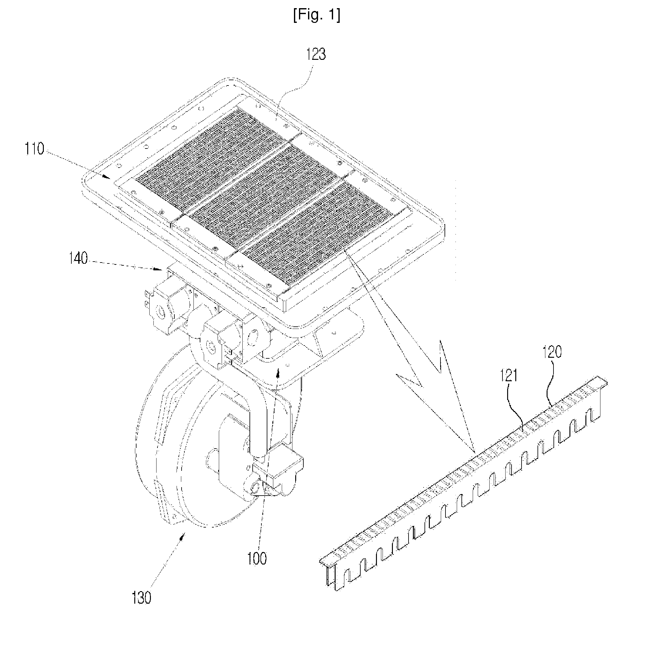
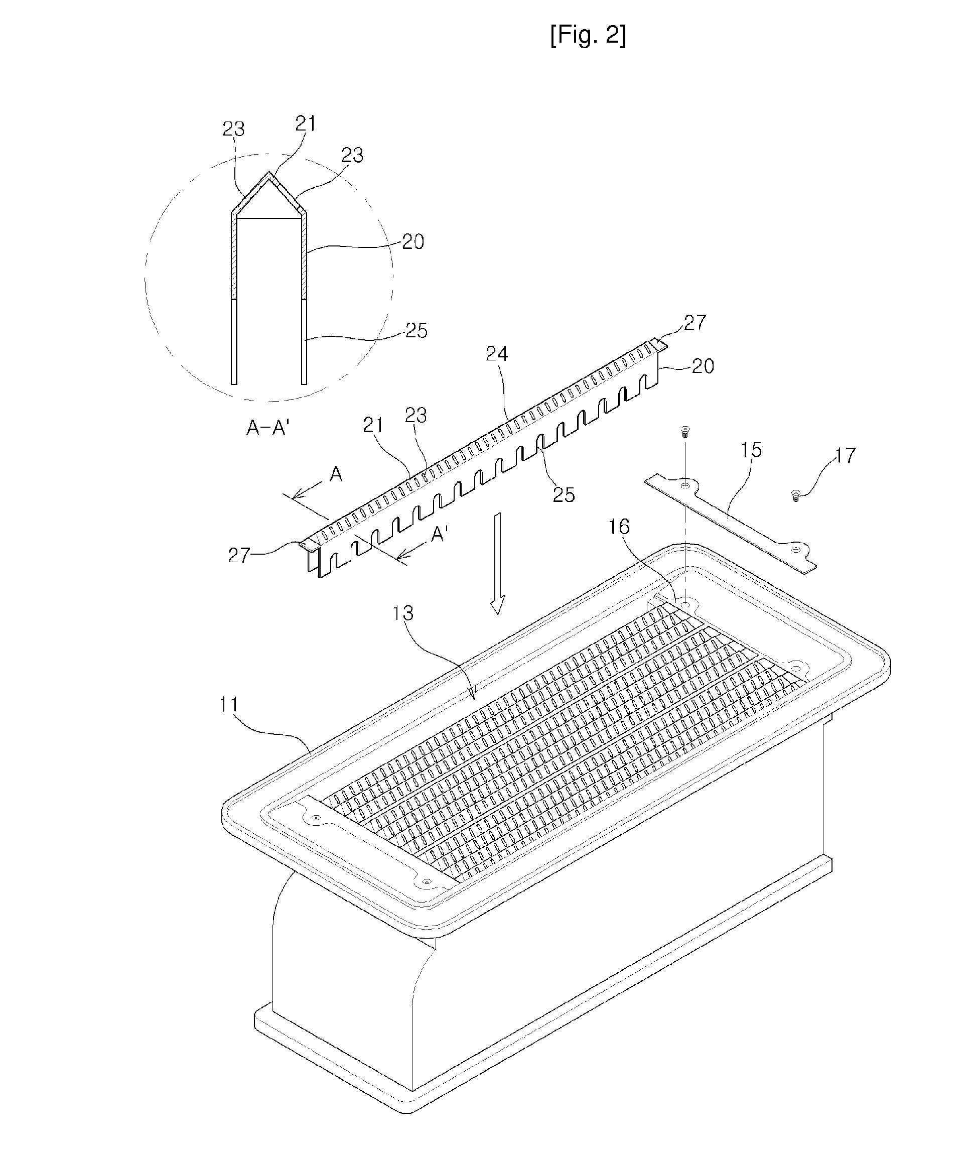
[0023]According to the present invention, there is provided a fire hole part structure provided to a premixing ignition burner which is installed to apply heat to the heat exchanger of a boiler, and including a plurality of fire hole pieces which are installed parallel to one another in mounting openings of a burner body and each of which is defined with a number of fire holes at regular intervals, wherein an upper wall of at least one of the fire hole pieces is bent or curved to extend in at least two directions, and the fire holes are defined through respective surface portions of the upper wall, which extend in different directions, to face different directions.

MODE FOR THE INVENTION

[0024]The above objects, and other features and advantages of the present invention will become more apparent after a reading of the following detailed description. Hereafter, a preferred embodiment of the present invention will be described with reference to the attached drawings.

[0025]FIG. 2 is a pe...


PUM


Abstract

A fire hole part structure of a gas burner, which is constructed to be manufactured at a low cost, can improve flame stability, and can prevent incomplete combustion due to the length of flame. The structure is provided to a premixing ignition burner, which is installed to apply heat to a heat exchanger of a boiler, and includes fire hole pieces which are installed parallel to one another in mounting openings of a burner body, and each of which is defined with fire holes at regular intervals. An upper wall of at least one of the fire hole pieces is bent or curved to extend in at least two directions, and the fire holes are defined through respective surface portions of the upper wall, which extend in different directions, to face different directions.

Description

TECHNICAL FIELD[0001]The present invention relates to a fire hole part structure of a gas burner, which can improve flame stability through impingement injection of flame through fire holes and can reduce the generation of incomplete combustion products.BACKGROUND ART[0002]As a gas burner for a boiler or a water heating system, a Bunsen burner was used in the past, but a premixing ignition type burner is being mainly used these days since it can reduce the generation of pollutants and decrease the size of a combustion chamber.[0003]The premixing ignition type burner has a fire hole part which has defined therein a plurality of fire holes for injecting the premixture of fuel gas and air to thereby produce flame. A conventional fire hole part has a structure in which fire holes are defined through a single plate member comprising a flat plate or a cylindrical plate. The conventional fire hole part structure has problems in that the combustion surface thereof is likely to be distorted ...

Claims


Application Information

Patent Timeline
IPC IPC(8): F23D14/84
CPCF23D14/58F23D14/586F23D2203/1026F23D2203/1017F23D2203/101F23D14/04F23D14/08
Inventor CHO, EUN SEONGCHO, SEUNG BEOM
Owner KYUNGDONG NAVIEN
Why Eureka
Try Eureka