Control apparatus for an internal combustion engine

a control apparatus and internal combustion engine technology, applied in the direction of electric control, combustion air/fuel air treatment, instruments, etc., can solve the problems of preventing the target amount of intake air from being achieved, and the actual flow rate of intake air is generated with respect, and achieve the effect of good target amount of intake air

Active Publication Date: 2009-11-26
MITSUBISHI ELECTRIC CORP
View PDF1 Cites 21 Cited by
  • Summary
  • Abstract
  • Description
  • Claims
  • Application Information

AI Technical Summary

Benefits of technology

[0014]According to the control apparatus for an internal combustion engine of the present invention, the relation between the effective opening area and the throttle opening is learned and corrected to achieve a good target amount of intake air, and a learning value thereof is appropriately stored. As a result, the control apparatus for an internal combustion engine, capable of controlling the throttle opening to precisely make the amount of intake air coincide with the target amount of intake air, can be obtained even when there are variations between the throttle bodies, various sensors, and the like, or various estimation errors.

Problems solved by technology

Moreover, a variation is also generated in the calculated opening area or effective opening area due to a variation between sensors for measuring the intake manifold pressure, the atmospheric pressure or the intake air temperature, or an error inherent in an estimation method.
As described above, there is a problem in that a variation is generated in the actual flow rate of intake air with respect to the target flow rate of intake air due to the variations between the throttle bodies, various sensors, and the like, or various estimation errors.
Thus, there arises a problem that a deviation is generated in the throttle opening for obtaining the target amount of intake air, which prevents the target amount of intake air from being achieved.

Method used


Image

  • Control apparatus for an internal combustion engine
  • Control apparatus for an internal combustion engine
  • Control apparatus for an internal combustion engine

Examples


first embodiment

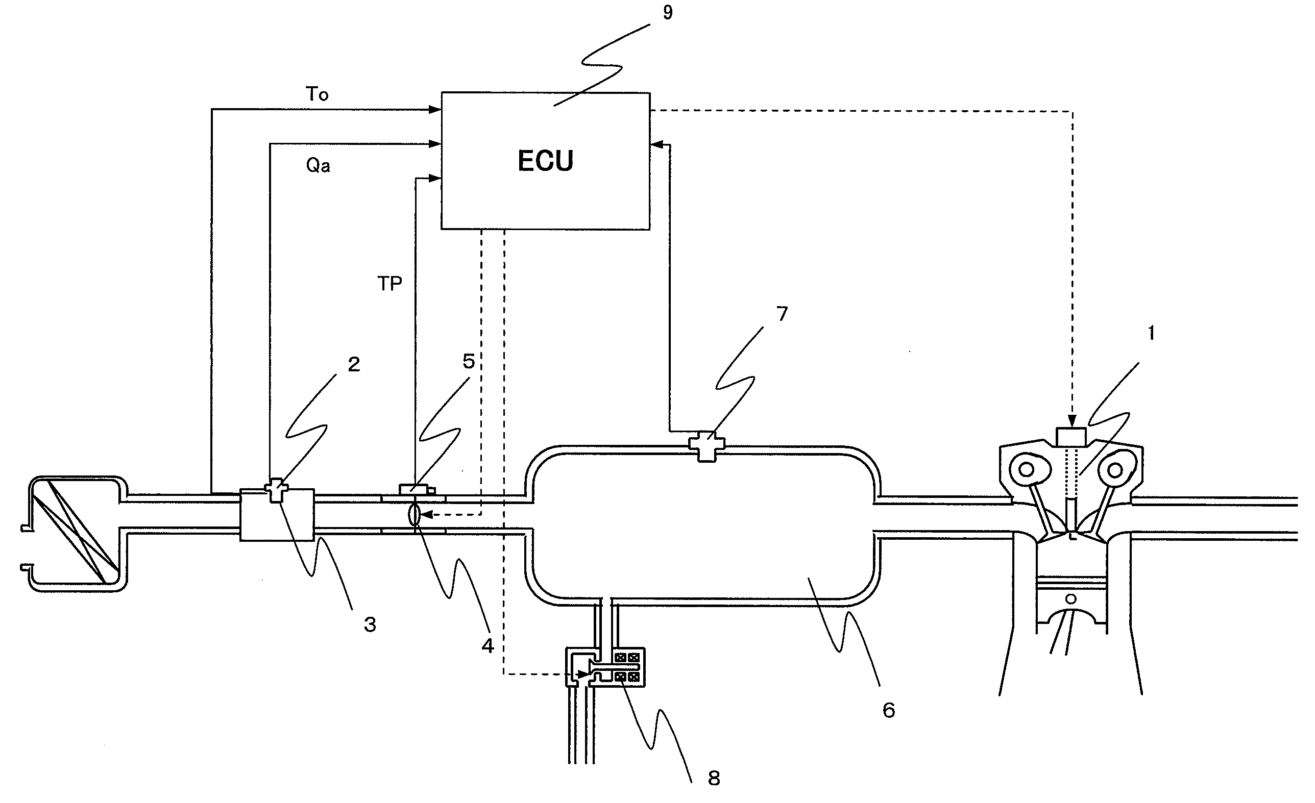
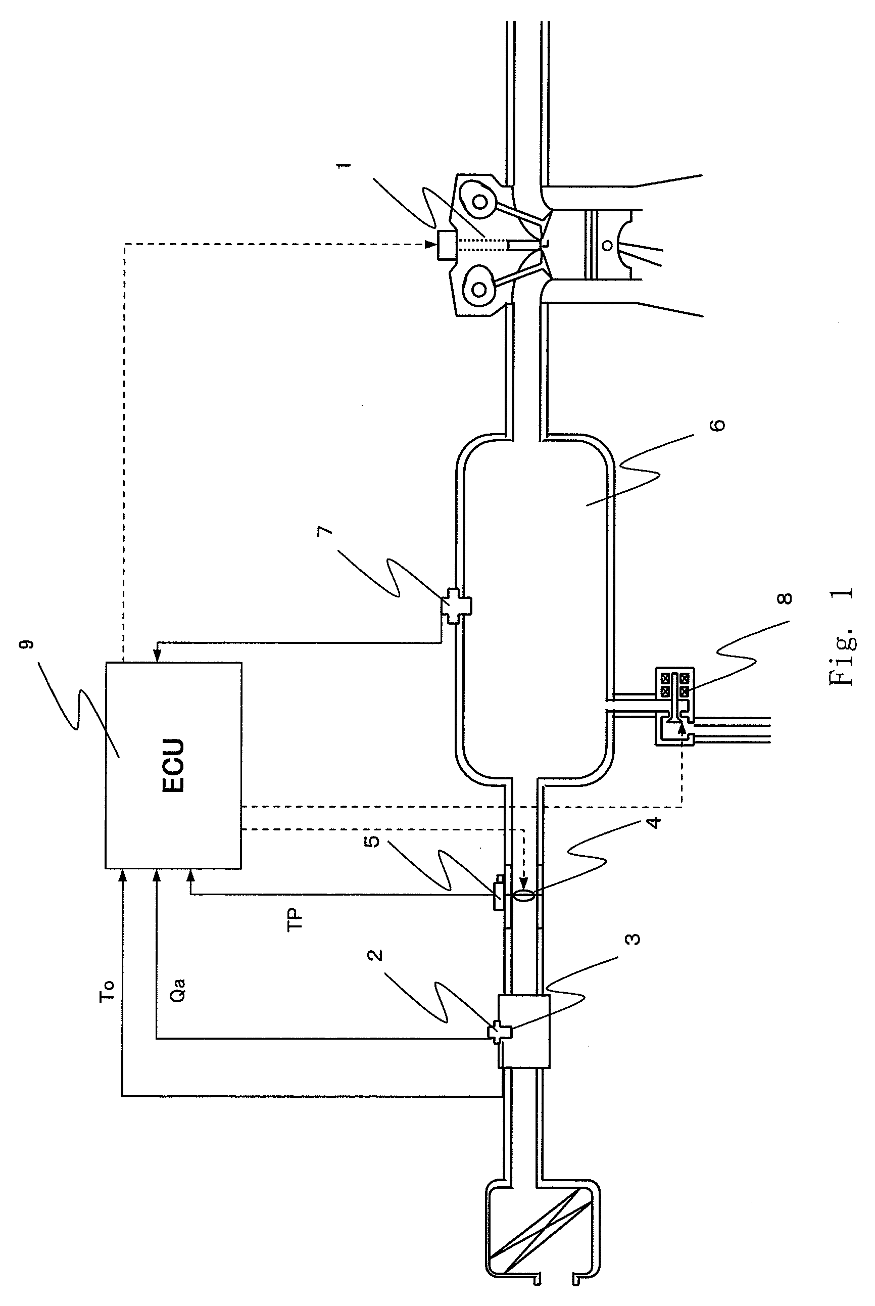
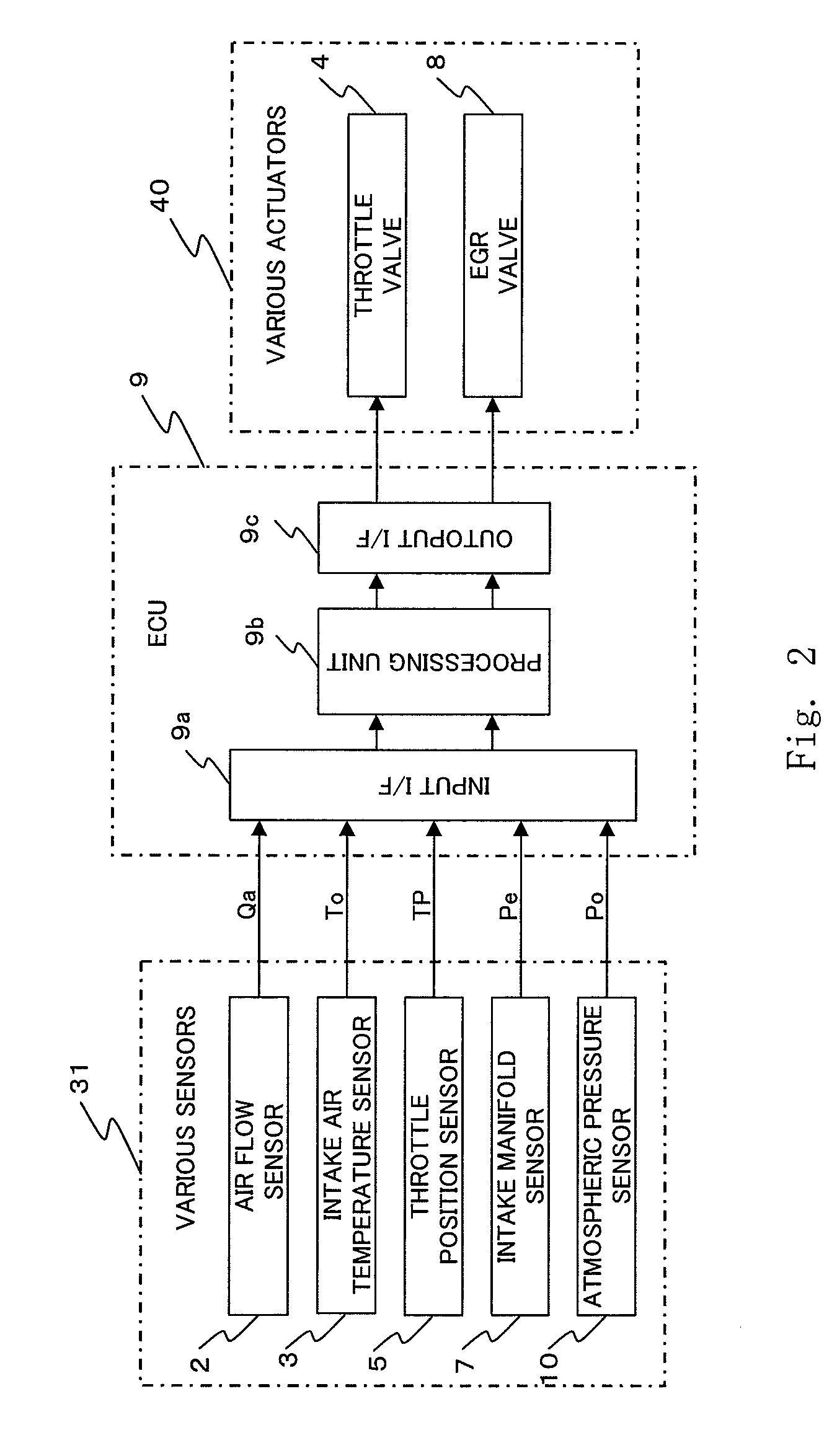
[0026]FIG. 1 is a configuration diagram schematically illustrating a control apparatus for an internal combustion engine in a first embodiment of the present invention. The control apparatus for an internal combustion engine in this first embodiment includes an engine 1, an air flow sensor 2, an intake air temperature sensor 3, a throttle valve 4, a throttle position sensor 5, a surge tank 6, an intake manifold pressure sensor 7, an EGR valve 8, and an electronic control unit 9 (hereinafter, referred to as “ECU 9”). FIG. 2 is a block diagram illustrating a schematic configuration of an engine control section of the control apparatus for an internal combustion engine in the first embodiment of the present invention, and schematically illustrates a peripheral configuration of the ECU 9.

[0027]In FIG. 1, at an upstream side of an intake passage that constitutes an intake system of the engine 1, there are arranged the air flow sensor 2 that measures the flow rate of intake air (hereinaft...


PUM


Abstract

The control apparatus for an internal combustion engine includes a throttle opening learning value calculation unit for calculating a throttle opening learning value based on a deviation between a target throttle opening and a learning throttle opening, controls the throttle opening by a learning corrected target throttle opening obtained by correcting the target throttle opening with the throttle opening learning value, and updates and stores a real-time learning value and a long time learning value based on a magnitude relation between values respectively obtained by adding the long time learning value to throttle openings respectively indicated by two effective opening area axis points of a correlation map, between which lies an actual effective opening area, and an actual throttle opening when the throttle opening learning value composed of the real-time learning value and the long time learning value is to be calculated.

Description

BACKGROUND OF THE INVENTION[0001]1. Field of the Invention[0002]The present invention relates to a control apparatus for an internal combustion engine, capable of controlling a throttle opening to obtain a target amount of intake air.[0003]2. Description of the Related Art[0004]Recently, there has been proposed a control apparatus for an internal combustion engine using an output shaft torque of an internal combustion engine (engine), which corresponds to a physical quantity directly acting on the control of a vehicle, as a requested value of a driving force from a driver or a vehicle side. In such a control apparatus for an internal combustion engine, good running performance is obtained by deciding the amount of air, the amount of fuel, and ignition timing corresponding to engine control quantities by using the output shaft torque as an output target value of the engine.[0005]In addition, it is generally known that a control quantity which has the greatest influence on the engine ...

Claims


Application Information

Patent Timeline
Patent Type & Authority Applications(United States)
IPC IPC(8): F02D41/00
CPCF02D11/10F02D41/18F02D41/2448F02D41/2464F02D41/248F02M35/10386F02M25/0743F02M35/10026F02M35/10222F02M35/1038F02D2200/0402F02M26/37
Inventor NISHIMURA, HIDEKIKANAZAWA, EIJI
Owner MITSUBISHI ELECTRIC CORP
Why Eureka
Try Eureka