Device for Controlling a Thermo-Electric System

a technology of thermoelectric system and control device, which is applied in the direction of lighting and heating apparatus, domestic cooling apparatus, instruments, etc., can solve the problems of limiting the affecting the actual temperature differential, and affecting the operation efficiency of the device, so as to increase the operating efficiency of the device

Inactive Publication Date: 2009-12-03
CARRIER CORP
View PDF12 Cites 22 Cited by
  • Summary
  • Abstract
  • Description
  • Claims
  • Application Information

AI Technical Summary

Benefits of technology

[0012]It is another object of the present invention to provide a control system for a thermo-electric device with the system achieving a real-time optimal efficiency for individual thermoelectric modules by regulating power supplied thereto.
[0021]It is an object of the present invention to provide a system for optimizing an operation of a thermo-electric module with a pellet to be operated at an optimal condition without externally altering the current flowing through an entire thermo-electric module of the system.

Problems solved by technology

This is because the material properties and the device operation limit the device's efficiency.
It has been observed that this known problem in the art is aggravated for large size thermo-electric cooling systems where many thermo-electric modules for a large area are used.
However, the actual temperature differential may not be uniform as expected.
This is a known problem and further imposes a difficulty in maintaining the temperature differential along the flow direction.

Method used


Image

  • Device for Controlling a Thermo-Electric System
  • Device for Controlling a Thermo-Electric System
  • Device for Controlling a Thermo-Electric System

Examples


Embodiment Construction

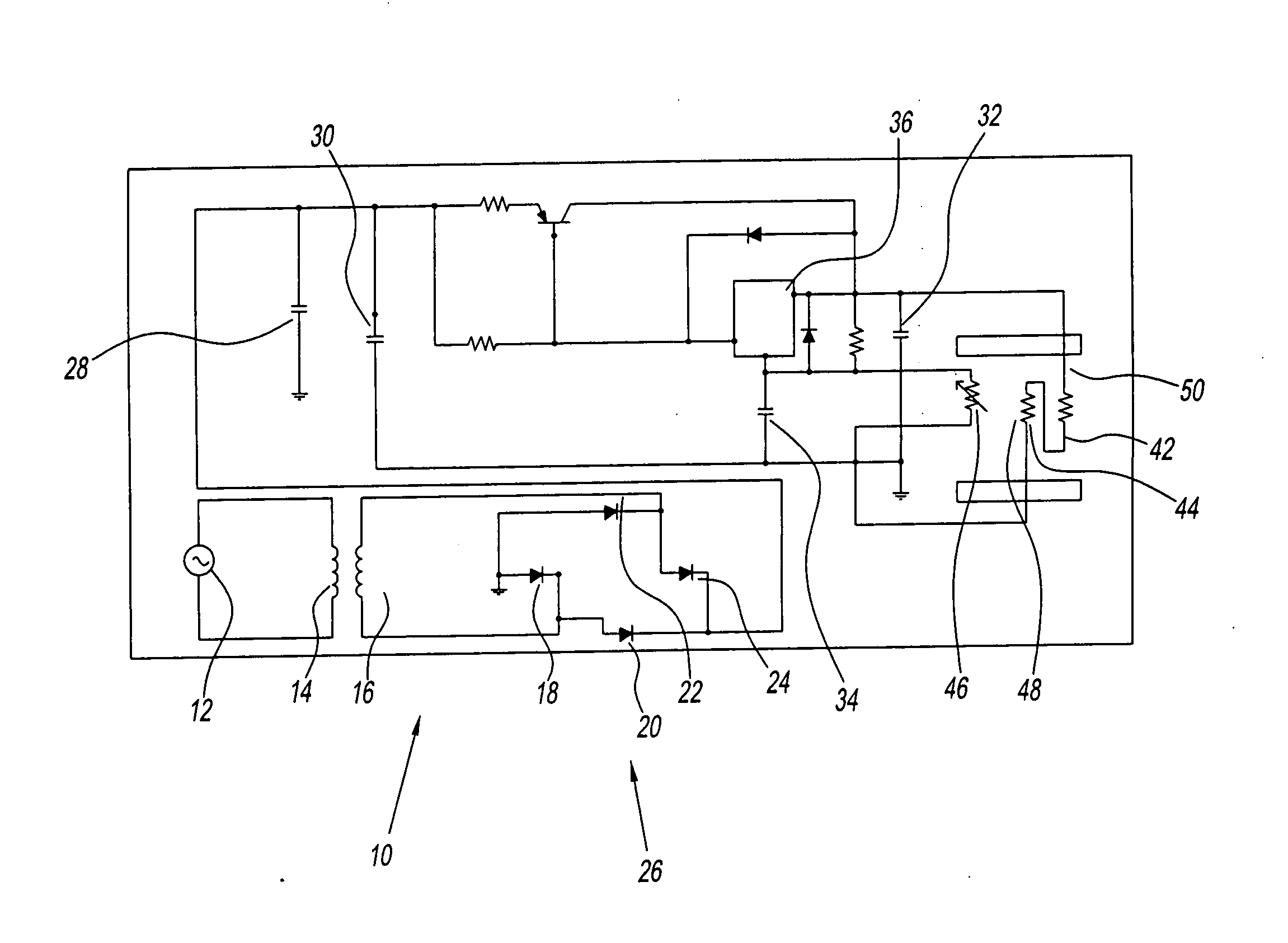
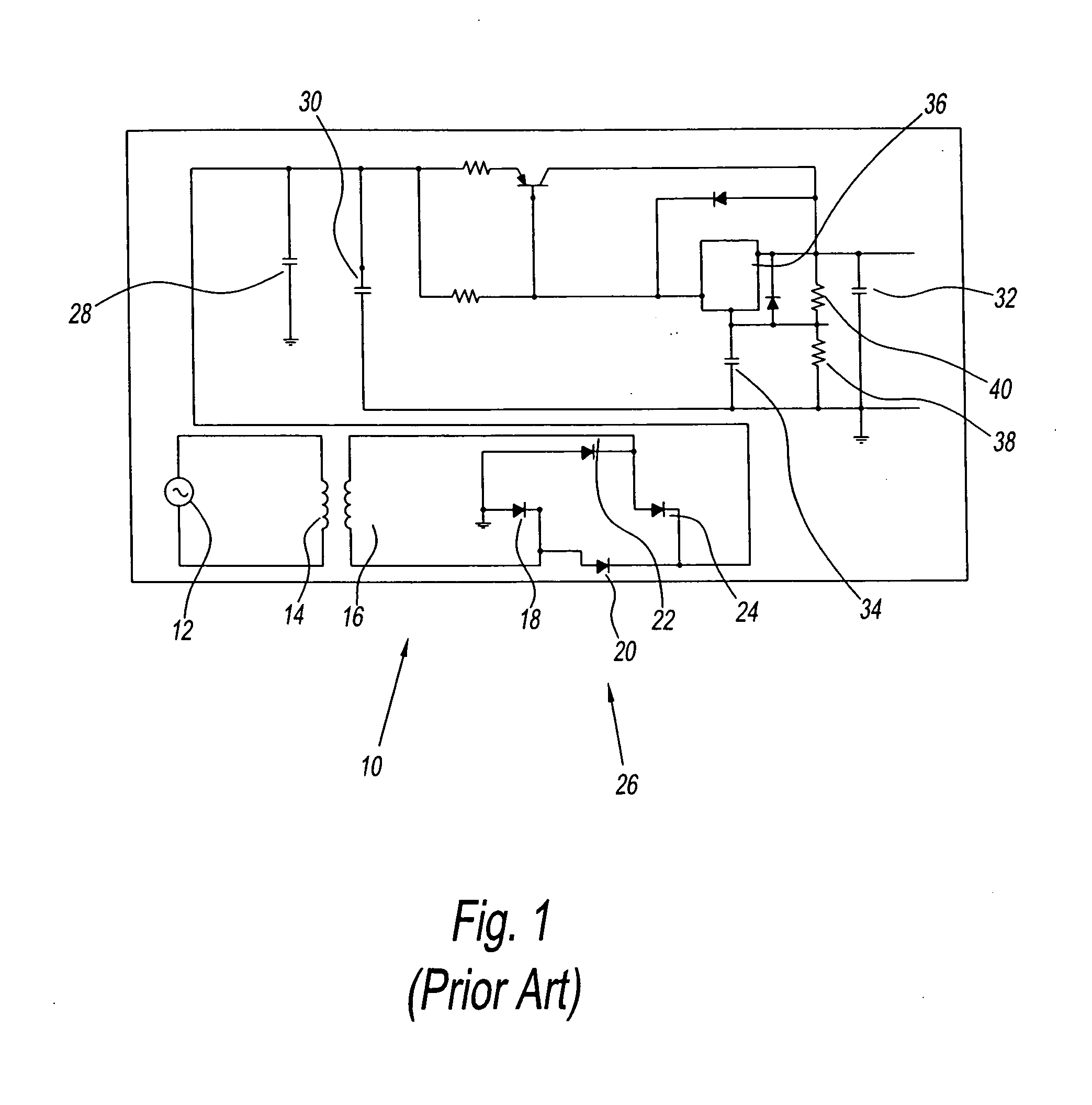
[0029]Referring to the figures and in particular FIG. 1, there is shown a prior art system 10 of an existing power regulating device. The system 10 has a power source preferably an alternating power source 12 connected to a first coil 14 that is spaced from a second coil 16. The first coil 14 and the second coil 16 preferably are a pair of inductive coils to reduce the voltage from the alternating power source 12 to the remainder of the circuit of the system 10. The second coil 16 is preferably connected to the diodes 18, 20, 22, 24 that form a full-wave rectifier generally represented by reference numeral 26 that converts the alternating power to a direct current. The second coil 16 is preferably center tapped and various designs for this transformer are well known in the art and are employed in practice.

[0030]The system 10 further has an input filter capacitor 28 connected to a filter capacitor 30 for a ripple rejection and to improve a power quality of the system 10. The prior ar...


PUM


Abstract

A control device for a thermo-electric device having a heat source side and a heat sink side. The control device has a detector for detecting a temperature difference between the heat source side and the heat sink side. The detector modulates a current for providing an optimal current to the thermo-electric device.

Description

BACKGROUND OF THE INVENTION[0001]1. Field of the Invention[0002]The present invention relates to a device for sensing a temperature differential between a heat source side and a heat sink side of a thermo-electric device and for regulating a current in response to the temperature differential. The present invention also more particularly relates to a device for providing an optimal current to the thermo-electric device and for a more productive operation of the thermo-electric device.[0003]2. Description of the Related Art[0004]Thermo-electric cooling and heating devices are well known in the art and are based on the Peltier effect. The device moves heat from one location to another when current flows through a predetermined semiconductor material having a p and n type semiconductor material or pellets. Historically, thermo-electric devices are used for spot cooling. This is because the material properties and the device operation limit the device's efficiency.[0005]Thermo-electric ...

Claims


Application Information

Patent Timeline
Patent Type & Authority Applications(United States)
IPC IPC(8): G05D23/24F25B21/02
CPCF25B21/02G05D23/2408F25B2321/0212G05D23/1906G05D23/24
Inventor CHEN, LEIYU, XIAOMEI
Owner CARRIER CORP
Why Eureka
Try Eureka