Liquid ejection method and liquid ejection apparatus

a liquid ejection and liquid ejection technology, which is applied in the direction of medical atomizers, inhalators, respirators, etc., can solve the problems of wasteful discharge of ink, increased costs, and impede the proper ejection of liquid

Inactive Publication Date: 2009-12-03
CANON KK
View PDF9 Cites 5 Cited by
  • Summary
  • Abstract
  • Description
  • Claims
  • Application Information

AI Technical Summary

Benefits of technology

[0011]The present invention provides a liquid ejection method and a liquid ejection apparatus which enables a small droplet of diameter at most 10 μm to be stably ejected and which allows a sufficient number of droplets to be ejected per unit time.
[0015]The present invention allows the liquid ejection head to eject the liquid so that variation in the length of the liquid column ejected from the ejection port in the liquid ejection head meets a predetermined condition. Thus, the liquid column is separated into a large number of sub-droplets, allowing a sufficient number of droplets to be ejected per unit time. For example, several tens of microlitters of small droplets each of about diameter 3 μm can be stably ejected every second. Such droplet ejections are suitable for allowing, in the field of medical care, a liquid drug to be sucked into the lungs in the form of a liquid mist.
[0016]Furthermore, a single operation of driving an energy generation portion generating energy required to eject ink allows a large number of sub-droplets to be formed. Thus, a sufficient number of droplets can be ejected per unit time by driving the energy generation portion only a few times. As a result, energy can be efficiently used to drive the liquid ejection head. This also allows the liquid ejection head to last long. The throttling portion between the ejection port and the individual liquid chamber is positioned in the liquid forming a meniscus in the ejection port. Thus, the liquid in the throttling portion is prevented from being clogged by drying. Therefore, the liquid can be continuously appropriately ejected from the beginning of the liquid ejection.

Problems solved by technology

However, when the size of the ejection port, that is, the diameter thereof, is smaller than 10 μm, the liquid in the ejection port changes rapidly as a result of drying or the like, hindering the liquid from being properly ejected.
Furthermore, if a recovery process is frequently executed to maintain proper liquid ejections, costs are increased, and ink is wastefully discharged.
On the other hand, in the development of a technique for reducing the size of the ejection port (in the example in Japanese Patent Laid-Open No. 2003-154665, the throttling portion pore) and thus the size of the ejected liquid droplet, an increase in the flow resistance of the liquid hinders the droplet from being properly ejected.
A thin throttling portion of thickness 1 μm may be damaged or broken by the flow of the liquid during ejection.
This hinders the liquid from being properly ejected.
Thus, in the conventional art, making the diameter of the throttle portion pore smaller than 3 μm is difficult.
Thus, in the conventional art, also in connection with the refilling of the liquid, making the diameter of the throttle portion pore smaller than 3 μm is difficult.

Method used


Image

  • Liquid ejection method and liquid ejection apparatus
  • Liquid ejection method and liquid ejection apparatus
  • Liquid ejection method and liquid ejection apparatus

Examples


first embodiment

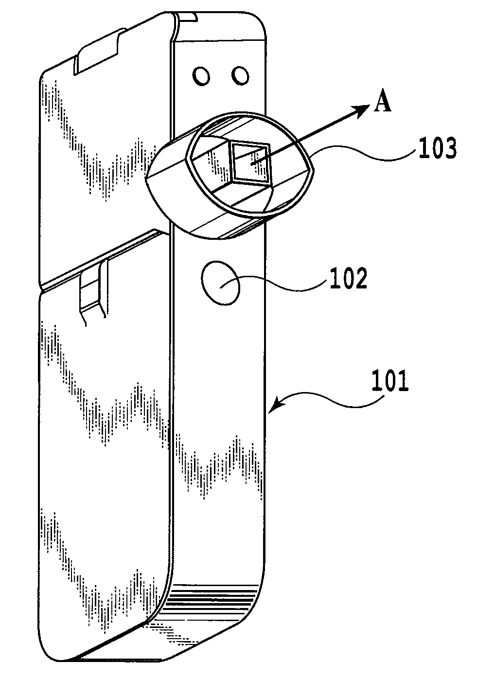
[0027]FIG. 4 is a perspective view of a liquid ejection apparatus to which the present invention is applicable. The liquid ejection apparatus in the present example is a medical suction apparatus used to allow a liquid drug (chemical) to be sucked into the lungs in the form of a liquid mist. A power switch 102 on an apparatus main body 101 is turned on to allow a driving circuit (not shown in the drawing) to drive a liquid ejection head. Then, the chemical stored in the apparatus main body 101 is ejected from the liquid ejection head in the direction of arrow A. The ejected and nebulized chemical is then sucked into the patient's mouth or the like through a mouthpiece 103.

[0028]FIG. 5 is a schematic perspective view illustrating an example of the basic configuration of the liquid ejection head. In the ejection head in the present example, electrothermal converters (heaters) 1 are used as energy generation portions that generate energy required to eject a liquid. That is, the heaters...

second embodiment

[0050]In a second embodiment, the voltage of a driving pulse applied to each heater 1 was set to be 1.5 times as high as that in the first embodiment. The other conditions are the same as those in the first embodiment.

[0051]As a result, a main droplet D1 of diameter 3 μm and succeeding six satellites D2 of diameter about 1 to 2 μm were generated. All of these seven droplets (D1 and D2) have sizes effective for treatment in the field of drug suction. Compared to Comparative Example 1, described below, the present embodiment increased the number of ejected droplets by 3.5-fold in spite of a slight increase in droplet diameter.

[0052]The process in which the satellite D2 was generated was observed. First, as is the case with the above-described embodiment, the liquid column projecting from the liquid surface of the chemical in an ejection port 4 was separated into the main droplet D1 and the liquid column C. Even with a slight variation from one chemical ejection operation to another, t...

third embodiment

[0056]In a third embodiment, a liquid ejection head was produced with the diameter of each pore 7 set to 5 μm. The voltage of a driving pulse applied to each heater 1 was set to 13.5 V. The other conditions are the same as those in the first embodiment.

[0057]As a result, a main droplet D1 of diameter 7 μm and succeeding four satellites D2 of diameter about 1 to 4 μm were generated. All of these five droplets (D1 and D2) have sizes effective for treatment in the field of drug suction. Compared to Comparative Example 1, described below, the present embodiment increased the number of ejected droplets by 2.5-fold in spite of a slight increase in droplet diameter.

[0058]The process in which the satellite D2 was generated was observed. First, as is the case with the above-described embodiments, a liquid column projecting from the liquid surface of the chemical in an ejection port 4 was separated into the main droplet D1 and the liquid column C. Even with a slight variation from one chemica...


PUM


Abstract

The present invention provides a liquid ejection method and a liquid ejection apparatus which enables small droplets each of diameter at most 10 μm to be stably ejected and which allows a sufficient number of droplets to be ejected per unit time. A heater is allowed to generate heat to eject a main droplet and a liquid column from an ejection port; the liquid column is to be separated into a plurality of sub-droplets. A relationship (L2 / L1)≧0.9 is set for the length L1 of the liquid column observed immediately after the liquid column has been separated from the main droplet and from a liquid in the ejection port and the length L2 of the liquid column observed immediately before the liquid column is separated into the plurality of droplets.

Description

BACKGROUND OF THE INVENTION[0001]1. Field of the Invention[0002]The present invention relates to a liquid ejection method and a liquid ejection apparatus which eject a fine droplet of liquid, and in particular, to a liquid ejection method and a liquid ejection apparatus which are suitably used in the medical field to allow a liquid drug to be sucked into the lungs in the form of a liquid mist.[0003]2. Description of the Related Art[0004]Keen examinations have been made of applications of liquid ejection apparatuses ejecting fine a droplet of liquid, in the fields of ink jet printing and medical care (particularly, the field of drug suction). Various such apparatuses have been proposed.[0005]For example, Japanese Patent Laid-Open No. 2003-154665 discloses a liquid ejection head in which individual liquid chambers and ejection ports through which ink is ejected are coupled together via throttling portions of pore diameter 3 μm to allow a droplet of diameter 3 μm (volume: 0.014 picolit...

Claims


Application Information

Patent Timeline
Patent Type & Authority Applications(United States)
IPC IPC(8): A61M15/00
CPCA61M11/001A61M15/0085A61M15/025
Inventor KITAKAMI, KOICHI
Owner CANON KK
Why Eureka
Try Eureka