Spinning apparatus, and apparatus and process for manufacturing nonwoven fabric

a technology of nonwoven fabric and spinning liquid, which is applied in the direction of turning machine accessories, drawing profiling tools, filament/thread forming, etc., can solve the problems of complex apparatus, waste of electrospinning energy, and difficult fibrous form of spinning liquid, etc., and achieves simple and energy-efficient, simple and energy-efficient apparatus

Inactive Publication Date: 2009-12-03
NIPPON BAIRIIN
View PDF7 Cites 17 Cited by
  • Summary
  • Abstract
  • Description
  • Claims
  • Application Information

AI Technical Summary

Benefits of technology

[0013]The spinning apparatus of [1] according to the present invention is a simple and energy-efficient apparatus capable of producing a nonwoven fabric consisting of fibers having a small fiber diameter.
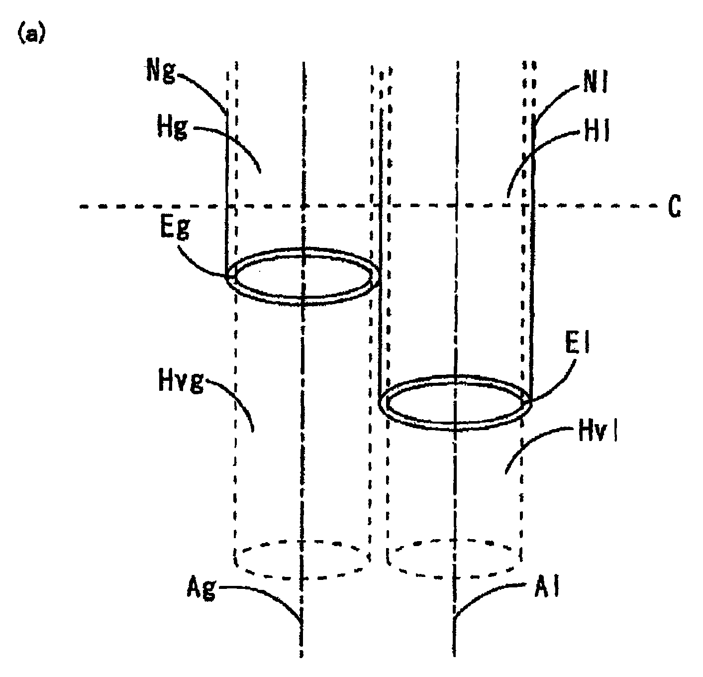
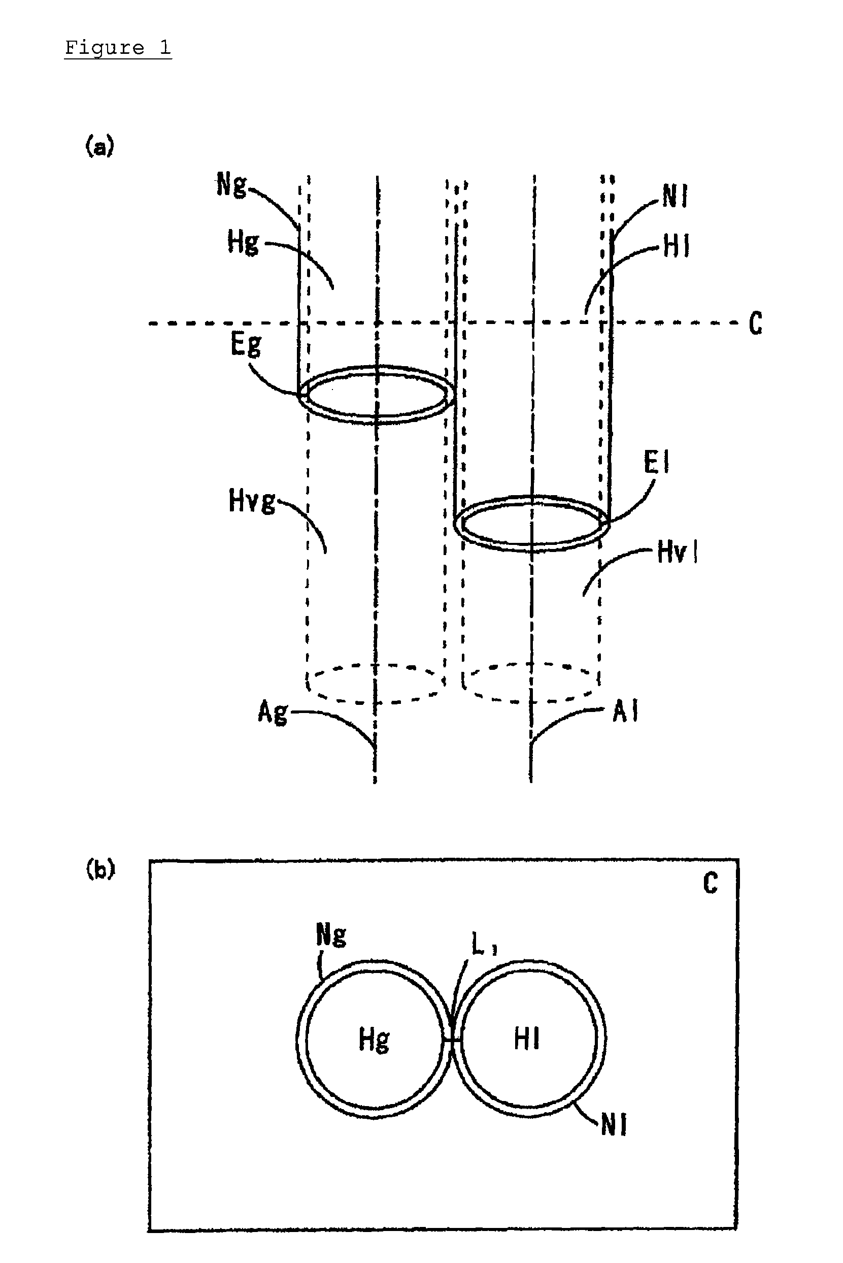
[0014]The spinning apparatus of [2] according to the present invention is “a spinning apparatus comprising an exit for extruding liquid, which is capable of extruding a spinning liquid, and an exit for ejecting gas, which is located upstream of each of the exits for extruding liquid and is capable of ejecting a gas, wherein(1) the spinning apparatus comprises a columnar hollow for liquid (Hl), in which the exit for extruding liquid forms one end of the columnar hollow for liquid,(2) the spinning apparatus comprises a columnar hollow for gas (Hg) of which one end is the exit for ejecting gas,(3) a virtual column for liquid (Hvl) which is extended from the columnar hollow for liquid (Hl) is located adjacent to a virtual column for gas (Hvg) which is extended from the columnar hollow for gas (Hg),(4) a central axis of an extruding direction in the columnar hollow for liquid (Hl) is parallel to a central axis of an ejecting direction in the columnar hollow for gas (Hg), and(5) when the columnar hollow for gas and the columnar hollow for liquid are cross-sectioned with a plane perpendicular to the central axis of the columnar hollow for gas, there exists only one straight line having the shortest distance between an outer boundary of the cross-section of the columnar hollow for gas (Hg) and an outer boundary of the cross-section of the columnar hollow for liquid (Hl)”.
[0015]In this apparatus, the spinning liquid extruded from the exit for extruding liquid is adjacent and parallel to the gas ejected from the exit for ejecting gas, and a shearing action of the gas and the accompanying airstream is single-linearly exerted on the spinning liquid, and therefore, fibers of which the diameter is thinned can be spun. This spinning apparatus is a simple and energy-efficient apparatus, because the application of a high voltage to the spinning liquid as well as the heating of the spinning liquid and the gas is not required.
[0016]The apparatus of [3] for manufacturing a nonwoven fabric, according to the present invention, comprises the fibers collection means, and therefore, fibers of which the diameter is thinned can be accumulated thereon to produce a nonwoven fabric.
[0017]In the process of [4] according to the present invention, when a gas having a flow rate of 100 m / sec. or more is ejected, generation of droplets can be avoided, and a nonwoven fabric comprising fibers of which the diameter is thinned can be efficiently produced.
[0018]The spinning apparatus of [5] according to the present invention is “a spinning apparatus comprising two or more exits for extruding liquid, which are capable of extruding a spinning liquid, and an exit for ejecting gas, which is located upstream of each of the exits for extruding liquid and is capable of ejecting a gas, wherein(1) the spinning apparatus comprises columnar hollows for liquid, in which each of the exits for extruding liquid forms one end of the corresponding columnar hollow for liquid,(2) the spinning apparatus comprises the columnar hollow for gas of which one end is the exit for ejecting gas,(3) each virtual column for liquid which is extended from each of the columnar hollows for liquid is located adjacent to the virtual column for gas which is extended from the columnar hollow for gas,(4) each central axis of the extruding direction in each of the columnar hollows for liquid is parallel to the central axis of the ejecting direction in the columnar hollow for gas, and(5) when the columnar hollow for gas and the columnar hollows for liquid are cross-sectioned with a plane perpendicular to the central axis of the columnar hollow for gas, there exists only one straight line having the shortest distance between the outer boundary of the cross-section of the columnar hollow for gas and an outer boundary of the cross-section of each of the columnar hollows for liquid, at any combination of the columnar hollow for gas and each of the columnar hollows for liquid”.

Problems solved by technology

It is necessary in the electrospinning that a high voltage should be applied to the nozzle or the fibers collection means, to apply an electrical field to the spinning liquid, and therefore, a complicated apparatus is needed and the electrospinning wastes energy.
However, because flat-shaped first, second, and third members are arranged parallel to each other in the apparatus, and the pressurized gas stream is applied to a sheet-like spinning liquid, it is considered that the spinning liquid is difficult to have a fibrous form and the nonwoven fabric contains a lot of droplets, and that, if fibers can be obtained, the diameter of the fibers would become thick.
However, because the pressurized gas stream is applied to a spinning liquid annularly extruded, spinning cannot be stably performed, and the spinning liquid is difficult to have a fibrous form and the nonwoven fabric contains a lot of droplets.

Method used

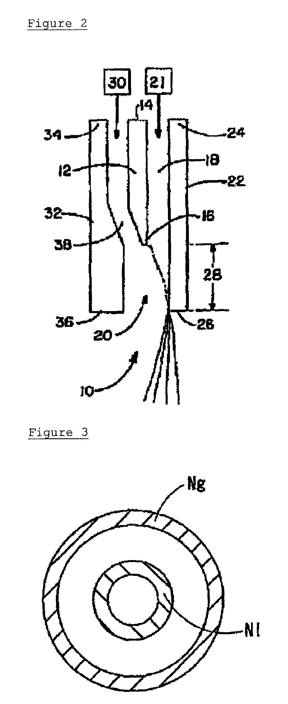

Image

  • Spinning apparatus, and apparatus and process for manufacturing nonwoven fabric
  • Spinning apparatus, and apparatus and process for manufacturing nonwoven fabric
  • Spinning apparatus, and apparatus and process for manufacturing nonwoven fabric

Examples


example 1

Preparation of Spinning Liquid

[0097]Polyacrylonitrile (manufactured by Aldrich) was dissolved in N,N-dimethylformamide so as to become a concentration of 10 mass % to prepare a spinning liquid (viscosity (temperature: 25° C.): 970 mPa·s).

(Preparation of Apparatus for Manufacturing Nonwoven Fabric) A manufacturing apparatus as shown in FIG. 1 comprising the following parts was prepared.

(1) Reservoir for spinning liquid: syringe

(2) Air supply equipment: compressor

(3) Nozzle for extruding liquid (Nl): metal nozzle

(3)-1 Exit for extruding liquid (El): circular, 0.4 mm in diameter (cross-sectional area: 0.13 mm2)

(3)-2 Columnar hollow for liquid (Hl): cylindrical, 0.4 mm in diameter

(3)-3 Outer diameter of nozzle: 0.7 mm

(3)-4 Number of nozzles: 1

(4) Nozzle for ejecting gas (Ng): metal nozzle

(4)-1 Exit for ejecting gas (Eg): circular, 0.4 mm in diameter (cross-sectional area: 0.13 mm2)

(4)-2 Columnar hollow for gas (Hg): Cylindrical, 0.4 mm in diameter

(4)-3 Outer diameter of nozzle: 0.7 mm

(4...

example 2

Preparation of Spinning Liquid

[0102]Polyacrylonitrile (manufactured by Aldrich) was dissolved in N,N-dimethylformamide so as to become a concentration of 10.5 mass % to prepare a spinning liquid (viscosity (temperature: 23° C.): 1100 mPa·s).

(Preparation of Apparatus for Manufacturing Nonwoven Fabric)

[0103]A manufacturing apparatus as shown in FIG. 4 comprising the following parts was prepared.

(1) Reservoir for spinning liquid: syringe

(2) Air supply equipment: compressor

(3) First nozzle for extruding liquid (Nl1): metal nozzle

(3)-1 First exit for extruding liquid (El1): circular, 0.33 mm in diameter (cross-sectional area: 0.086 mm2)

(3)-2 First columnar hollow for liquid (Hl1): cylindrical, 0.33 mm in diameter

(3)-3 Outer diameter of nozzle: 0.64 mm

(4) Second nozzle for extruding liquid (Nl2): metal nozzle

(4)-1 Second exit for extruding liquid (El2): circular, 0.33 mm in diameter (cross-sectional area: 0.086 mm2)

(4)-2 Second columnar hollow for liquid (Hl2): cylindrical, 0.33 mm in dia...

example 3

Preparation of Spinning Liquid

[0105]Polyacrylonitrile (manufactured by Aldrich) was dissolved in N,N-dimethylformamide so as to become a concentration of 8 mass % to prepare spinning liquid A (viscosity (temperature: 23° C.): 500 mPa·s).

[0106]Further, polyacrylonitrile (manufactured by Aldrich) was dissolved in N,N-dimethylformamide so as to become a concentration of 11 mass % to prepare spinning liquid B (viscosity (temperature: 23° C.): 1600 mPa·s).

(Preparation of Apparatus for Manufacturing Nonwoven Fabric)

[0107]The manufacturing apparatus described in Example 2 was prepared.

(Manufacture of Nonwoven Fabric)

[0108]Fibers were accumulated on the fibers collection means (net) under the following conditions to produce a nonwoven fabric. A nonwoven fabric having an excellent uniformity could be produced without the scattering of fibers and with a high productivity. Fibers having an average fiber diameter of 0.2 μm and fibers having an average fiber diameter of 0.4 μm were uniformly mix...


PUM

PropertyMeasurementUnit
diameteraaaaaaaaaa
distanceaaaaaaaaaa
distanceaaaaaaaaaa

Abstract

A spinning apparatus comprising one or more exits for extruding liquid, and an exit for ejecting gas, located upstream of the exits for extruding liquid, wherein the apparatus comprises a columnar hollow for liquid, in which the exit for extruding liquid forms one end of the columnar hollow; the apparatus comprises a columnar hollow for gas having the exit for ejecting gas; a virtual column for liquid, extended from the columnar hollow for liquid, is adjacent to a virtual column for gas, extended from the columnar hollow for gas; the central axis of the columnar hollow for liquid is parallel to the central axis of the columnar hollow for gas; and there exists only one straight line having the shortest distance between an outer boundary of the cross-section of the columnar hollow for gas and an outer boundary of the cross-section of the columnar hollow for liquid, is disclosed.

Description

TECHNICAL FIELD[0001]The present invention relates to a spinning apparatus, an apparatus comprising the same for manufacturing a nonwoven fabric, and a process for manufacturing a nonwoven fabric using the nonwoven fabric manufacturing apparatus.BACKGROUND ART[0002]Fibers having a small fiber diameter can impart various excellent properties, such as a separating property, a liquid-holding capacity, a wiping property, a shading property, an insulating property, or flexibility, to a nonwoven fabric, and therefore, it is preferable that fibers which form a nonwoven fabric have a small fiber diameter. As a process for manufacturing such fibers having a small fiber diameter, electrospinning is known. In this process, a spinning liquid is extruded from a nozzle, and at the same time, an electrical field is applied to the extruded spinning liquid to thereby draw the spinning liquid and thin the diameter of the spinning liquid, and fibers are directly collected on a fibers collection means ...

Claims


Application Information

Patent Timeline
Patent Type & Authority Applications(United States)
IPC IPC(8): B29C47/10D04H3/16
CPCD01D5/0985D01D4/025D01D4/02D01D5/00D04H1/56
Inventor MATSUBAYASHI, YASUKOAMAGASA, MASAHIROKOJIMA, YUKIOMURATA, SYUICHI
Owner NIPPON BAIRIIN
Why Eureka
Try Eureka